
Positive-fit connection between a metallic link and an injection-moulded plastic part notably for spectacles

a technology of injection moulding and plastic parts, which is applied in the direction of shrinkage connections, optics, instruments, etc., can solve the problems of unsuitable conventional plug-in connections, unable to automate the insertion of metallic parts into injection moulds, and damage to the surface of frequently refined metallic parts

Inactive Publication Date: 2002-03-19
SILHOUETTE INT SCHMIED
View PDF10 Cites 30 Cited by
  • Summary
  • Abstract
  • Description
  • Claims
  • Application Information

AI Technical Summary

Benefits of technology

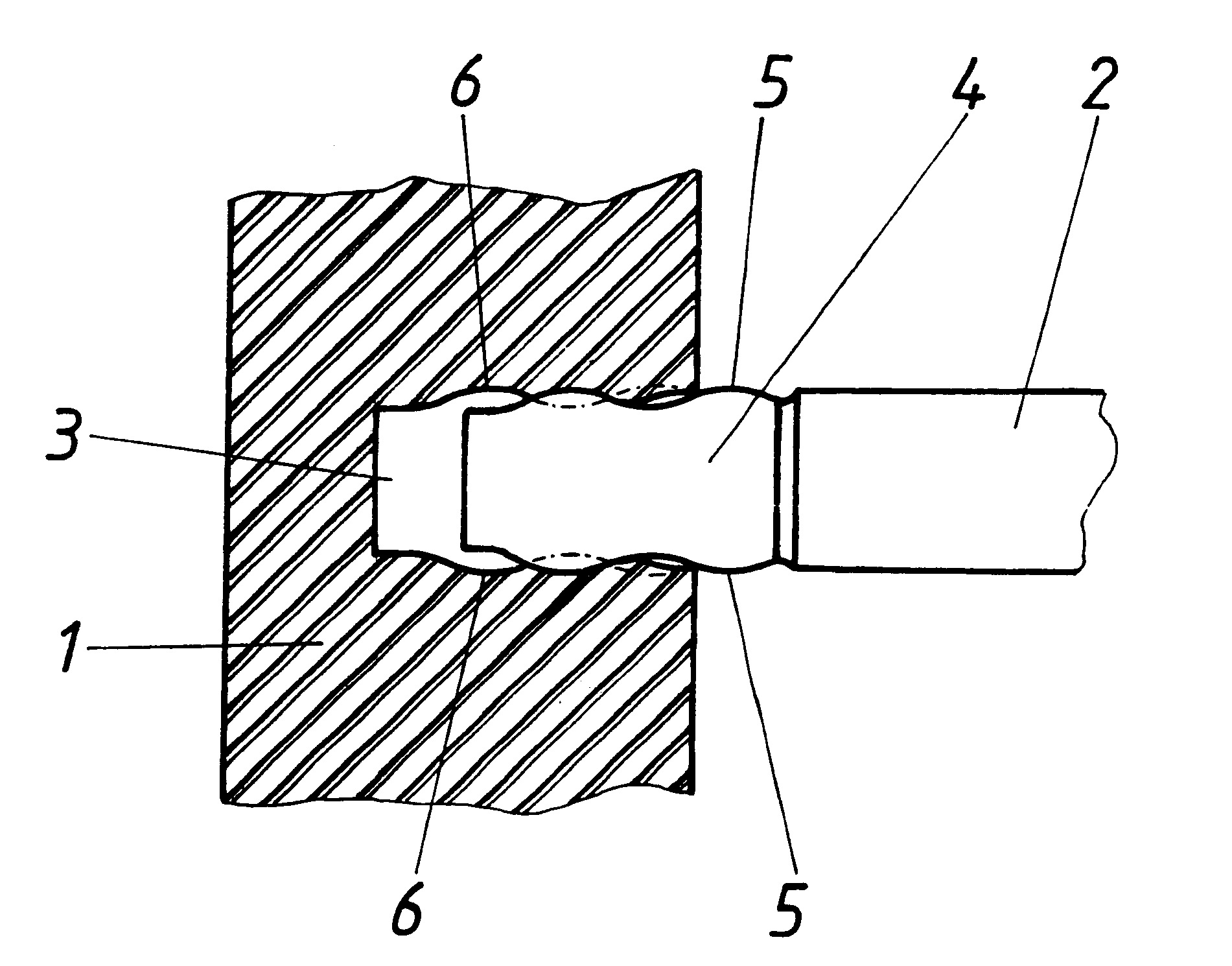
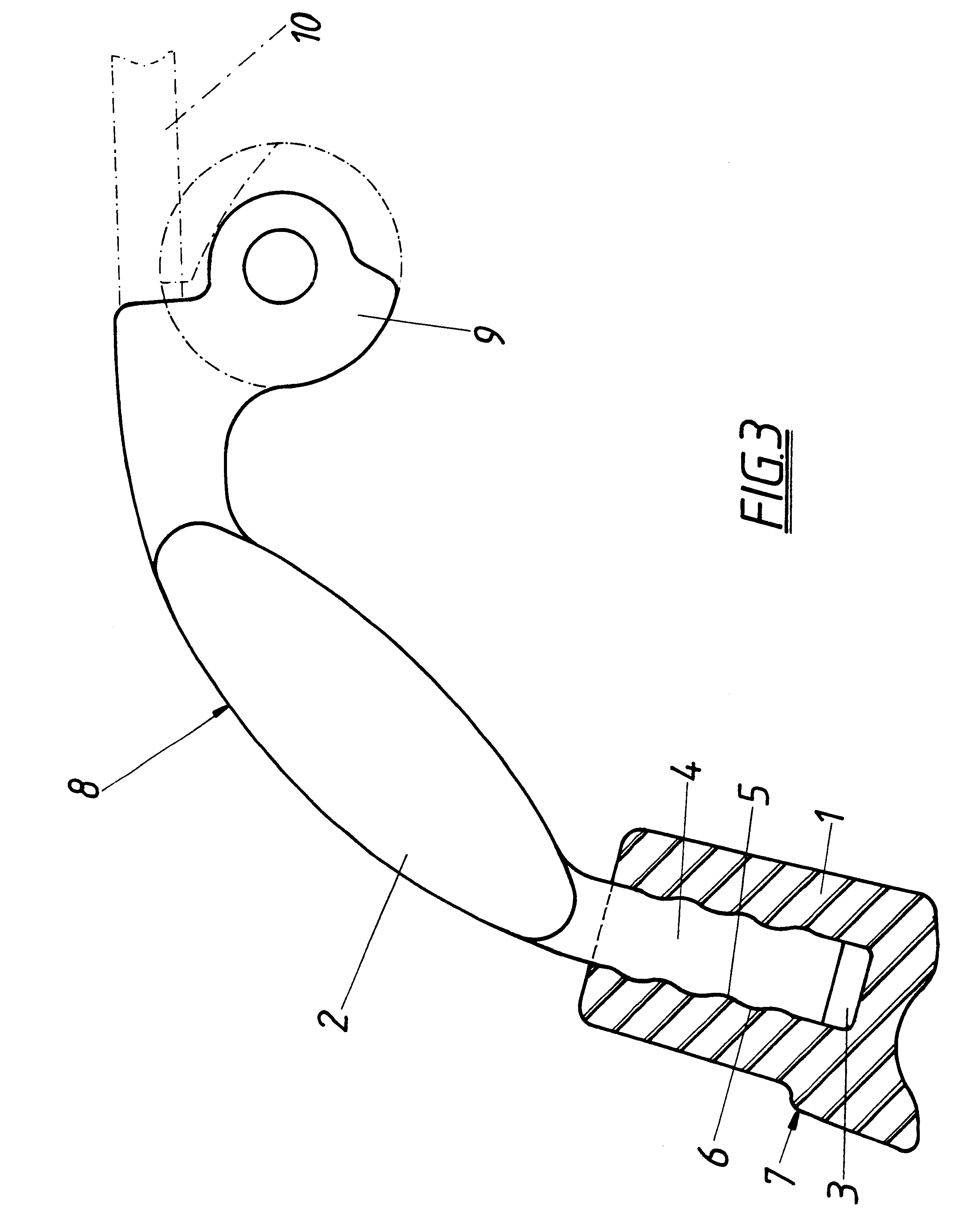
The positive-locking connection between a metallic bridge and a moulded article which is injection-moulded from plastic allows new spectacle designs because the plug-in connection can also be made as late as during the assembly. It becomes possible for example to advantageously produce spectacle joints which consist of a cylindrical joint body which is rotatably held in the bearing bush of the cheek piece and which is connected with the wire side shaft. Since the wire side shaft of the spectacle is guided through a circumferential slot of the bearing bush and the cylindrical joint body can only be inserted axially into the bearing bush, it was necessary that the circumferential slot was provided with an axial leadthrough opening for the wire side shaft in order to enable the insertion of the wire side shaft connected with the joint body into the side joint. If the bearing body which is produced as a moulded part made of injection-moulded plastic forms a plug-in receiving means in accordance with the invention for the engaging end of the wire side shaft and if the engaging end of the wire side shaft is provided with a respective snap-in profiling, the engaging end of the wire side shaft, following the axial insertion of the joint body into the bearing bush, can be inserted from the outside through the circumferential slot of the bearing bush in the radial direction into the plug-in receiving means in order to ensure the required positive-locking connection. In this way, an axial retention of the joint body in the bearing bush is achieved which is effective over the entire swivelling range of the joint, namely with the help of the wire side shaft which is held in the circumferential slot of the bearing bush against a single displacement.
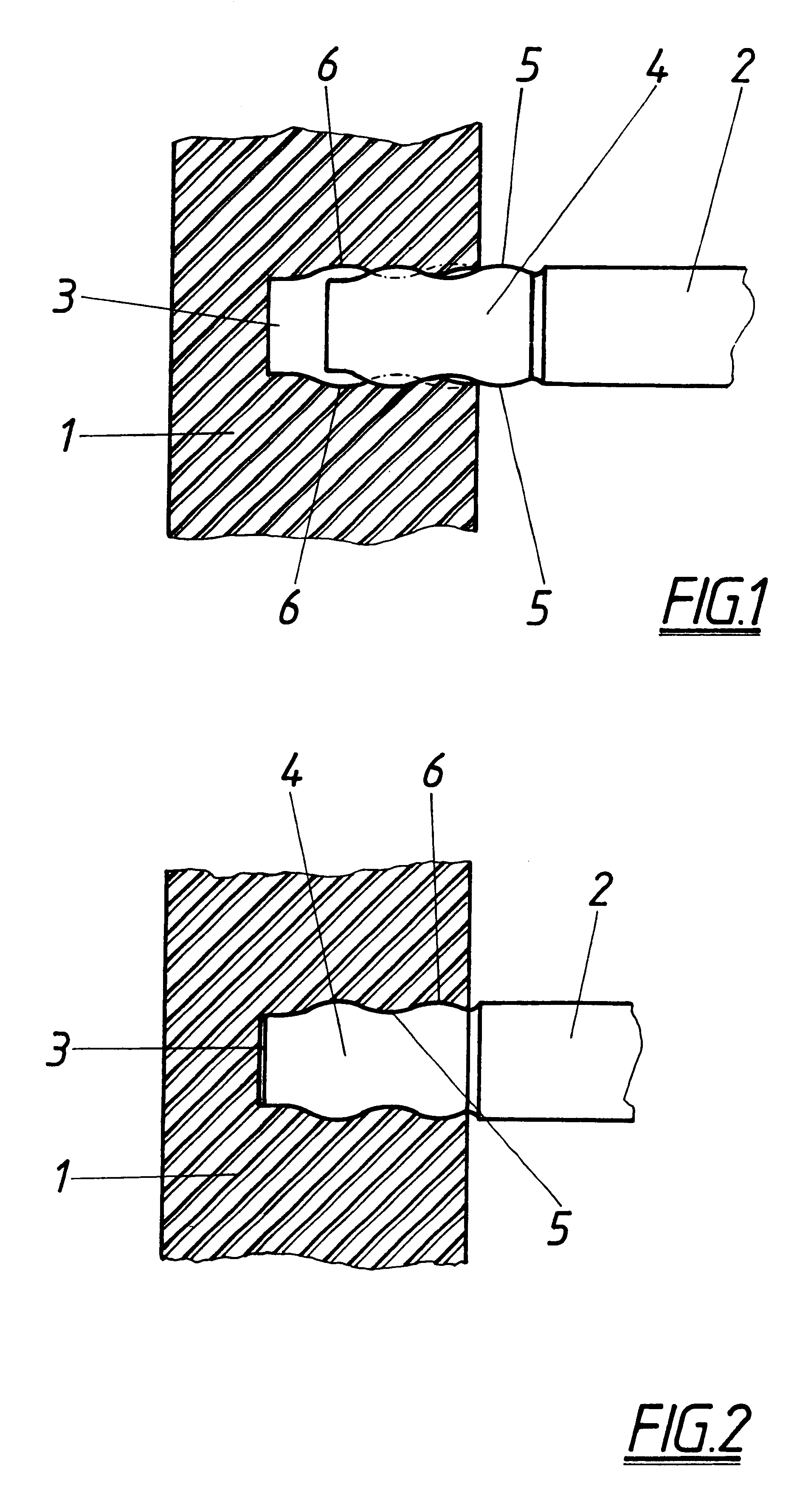
As has already been explained above, it is of relevant importance for the permanent resilience of the positive-locking connection that the wave-like snap-in profiling of the bridge end corresponds to the wall profiling of the plug-in receiving means, so that in the case of engagement no locally limited tensions will occur in the moulded article which could lead to an overload of the plastic although the connection stress remains within a permissible range. In order to enable the simple production of a respective plug-in receiving means for the engaging end of the metallic bridge which is provided with a wave-like snap-in profiling, an injection mould with a core for the plug-in receiving means can be provided for the moulded article which has the shape of the engaging end of the bridge. Since a moulded article with such a plug-in receiving means cannot be removed from the mould with ease and the elastic behaviour of the moulded article still must allow the insertion of the engaging end of the metallic bridge into the plug-in receiving means, the core, following the curing of the moulded article, can be pulled out by using the elastic behaviour of the wall profiling of the plug-in receiving means from the moulded article under elastic deformation of the wall profiling, so that advantageous constructional conditions for the injection moulds and simple mould removal conditions are obtained for the respective moulded articles which are produced with such injection moulds.

Problems solved by technology

Due to the unavoidable tolerances, it may occur that there are difficulties in sealing the leadthrough of the metallic cheek piece through the injection mould, so that in the visible zone of the transition from the plastic frame to the metallic cheek piece it is necessary to rework the cheek piece.
Moreover, it may occur that the surface of the frequently refined metallic parts is damaged by the insertion into the injection mould.
An additional factor is that the insertion of the metallic parts into the injection mould can hardly be automated.
Conventional plug-in connections are unsuitable for such use due to the relatively high load requirements which are placed on spectacle frames.

Method used


Image

  • Positive-fit connection between a metallic link and an injection-moulded plastic part notably for spectacles
  • Positive-fit connection between a metallic link and an injection-moulded plastic part notably for spectacles
  • Positive-fit connection between a metallic link and an injection-moulded plastic part notably for spectacles

Examples


Embodiment Construction

As is shown in FIGS. 1 and 2, the moulded article 1, which is injection-moulded from plastic, is provided with a plug-in receiving means 3 for the engaging end 4 of bridge 2 for the purpose of connection with a metallic bridge 2. Said plug-in receiving means 3 is provided with a rectangular cross-section-like engaging end 4, with said engaging end 4 being arranged on mutually opposite bridge surfaces with a wave-like snap-in profiling 5. Since the plug-in receiving means 3 is provided with a wall profiling 6 which corresponds to the snap-in profiling 5, the engaging end 4 of the bridge 2 which is inserted into the plug-in receiving means 3 is connected in a positive-locking way with the moulded article 1, as is shown in FIG. 2. During the insertion of the engaging end 4 into the plug-in receiving means 3 it is necessary that the moulded article 1 allows sufficient elastic deformation in the zone of the wall profiling 6 in order to enable the wave crests of the snap-in profiling 5 of...


PUM


Abstract

In a positive-locking connection between a metallic bridge and a moulded article which is injection-moulded from plastic, in particular for spectacles, one end of the bridge engages in the moulded article. In order to provide advantageous constructional conditions, it is proposed that the moulded article form a plug-in receiving means with the engaging end of the bridge which is provided with a wave-like snap-in profiling and can be inserted into the plug-in receiving means under a substantially elastic deformation of a wall profiling of the receiving means which is shaped according to the snap-in profiling of the bridge end.

Description

The invention relates to a positive-locking connection between a metallic bridge and a moulded article which is injection-moulded from plastic, in particular for spectacles, with one end of the bridge engaging in the moulded article.STATE OF THE ARTIn order to connect the metallic cheek piece carrying the side joint with the plastic frame forming the frame for the glasses in such a way that this connection can be sufficiently loaded, the metallic cheek piece is inserted with its engaging end into the injection mould for the spectacle frame, so that the plastic of the frame is injection-moulded around the engaging end of the cheek piece. Due to the unavoidable tolerances, it may occur that there are difficulties in sealing the leadthrough of the metallic cheek piece through the injection mould, so that in the visible zone of the transition from the plastic frame to the metallic cheek piece it is necessary to rework the cheek piece. Moreover, it may occur that the surface of the frequ...

Claims


Application Information

Patent Timeline
Patent Type & Authority Patents(United States)
IPC IPC(8): F16B17/00F16B4/00G02C5/14G02C5/00G02C5/22
CPCF16B4/004F16B17/006G02C5/22G02C5/10G02C5/00
Inventor SPINDELBALKER, RUPERT
Owner SILHOUETTE INT SCHMIED
Learn More