
Co-operative control system for a vehicle

a technology of cooperative control and vehicle, applied in the direction of process and machine control, gearing, instruments, etc., can solve the problems of unsatisfactory steering force and driver experience a disagreeable sensation

Inactive Publication Date: 2002-03-19
HONDA MOTOR CO LTD
View PDF8 Cites 40 Cited by
  • Summary
  • Abstract
  • Description
  • Claims
  • Application Information

AI Technical Summary

Benefits of technology

In accordance with the above-mentioned arrangement, when the electric power steering device or the second control means malfunctions and, as a result, the torque steer phenomenon accompanying the operation of the force distribution device cannot be lessened, the first control means stops the operation of the force distribution device, so preventing the aforementioned torque steer phenomenon from occurring. It is thus possible to prevent the driver from experiencing a disagreeable sensation.
In accordance with a first refinement of the basic invention, a co-operative control system for a vehicle is proposed wherein when the malfunction occurs during the operation of the force distribution device, the first control means gradually decreases the absolute value of the difference between the distributed forces of the force distribution device to the right and left wheels towards zero.
In accordance with the above-mentioned arrangement, when the aforementioned malfunction occurs during the operation of the force distribution device, since the absolute value of the difference between the distributed forces of the force distribution device to the right and left wheels gradually decreases towards zero, a rapid change in the steering reaction, which could be experienced by the driver from the steering wheel can be prevented.
If the aforementioned malfunction occurs when the force distribution system generates a distributed force which is larger than the reference distributed force, torque steer is caused which turns the vehicle sharply towards the inside in the turning direction, but in accordance with the invention, since the distributed force is immediately decreased to a level smaller than the aforementioned reference distributed force when a malfunction occurs, it is possible to prevent the occurrence of the torque steer phenomenon which turns the vehicle sharply towards the inside in the turning direction. Moreover, since the absolute value of the difference between the distributed forces of the distribution device to the right and left wheels is subsequently decreased gradually towards zero, the steering reaction is prevented from changing rapidly.

Problems solved by technology

In a vehicle having such a driving force distribution device, there is a disadvantage in that when the driving forces distributed to the right and left driven wheels are varied, an undesirable steering force is produced in the right and left driven wheels that also serve as steered wheels (the torque steer phenomenon).
In a vehicle carrying out the above-mentioned co-operative control, when the electric power steering device malfunctions and a steering assist torque cannot be generated, the torque steer phenomenon caused by the operation of the driving force distribution device cannot be counteracted and there is a possibility that the driver might experience a disagreeable sensation.

Method used


Image

  • Co-operative control system for a vehicle
  • Co-operative control system for a vehicle
  • Co-operative control system for a vehicle

Examples


Embodiment Construction

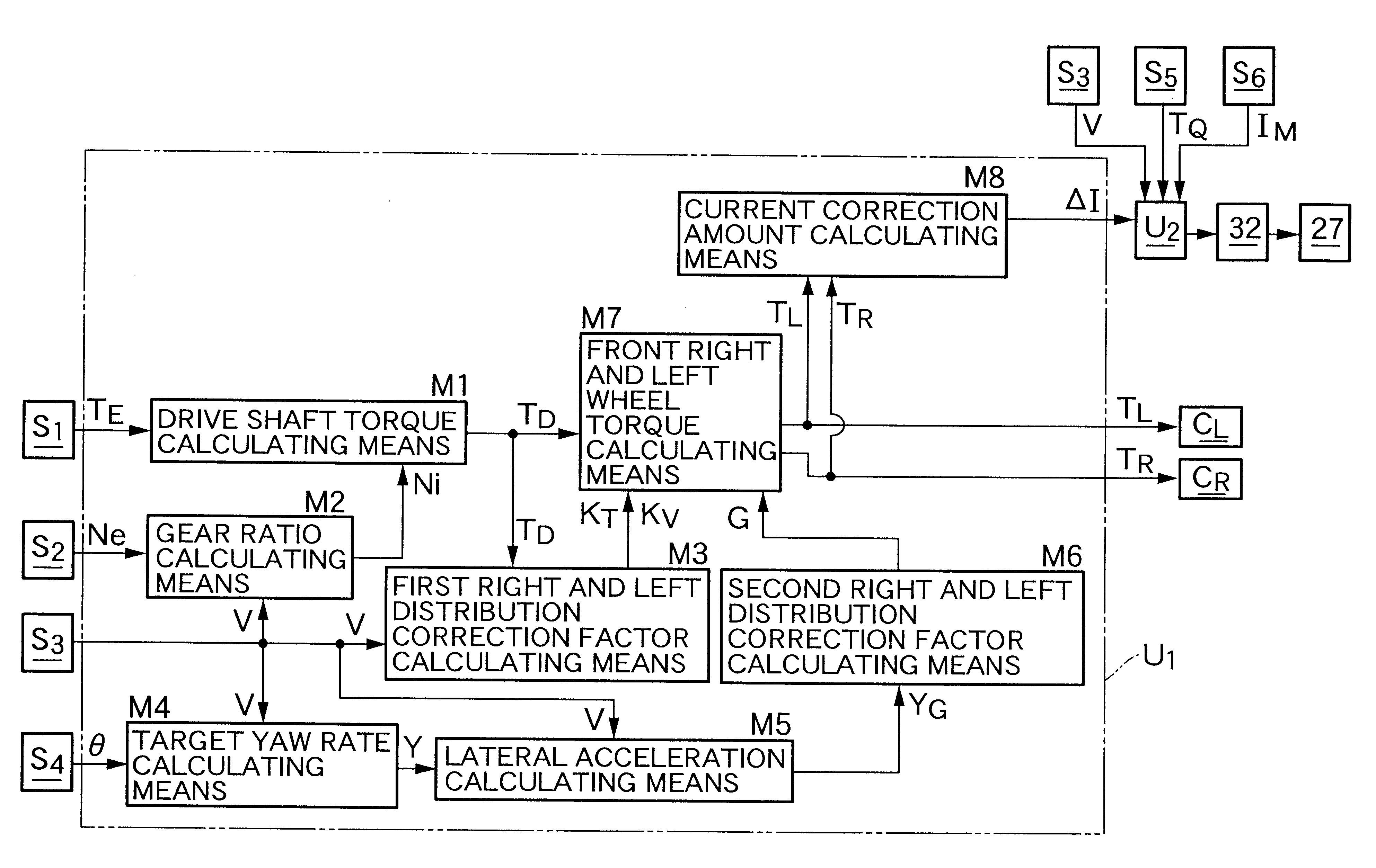
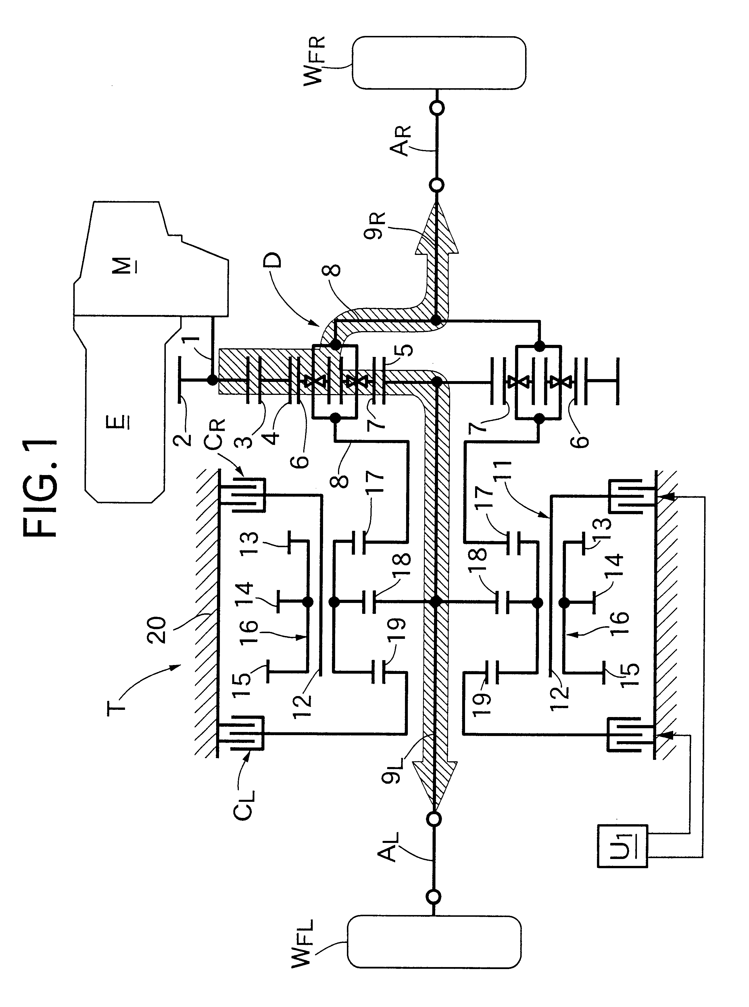
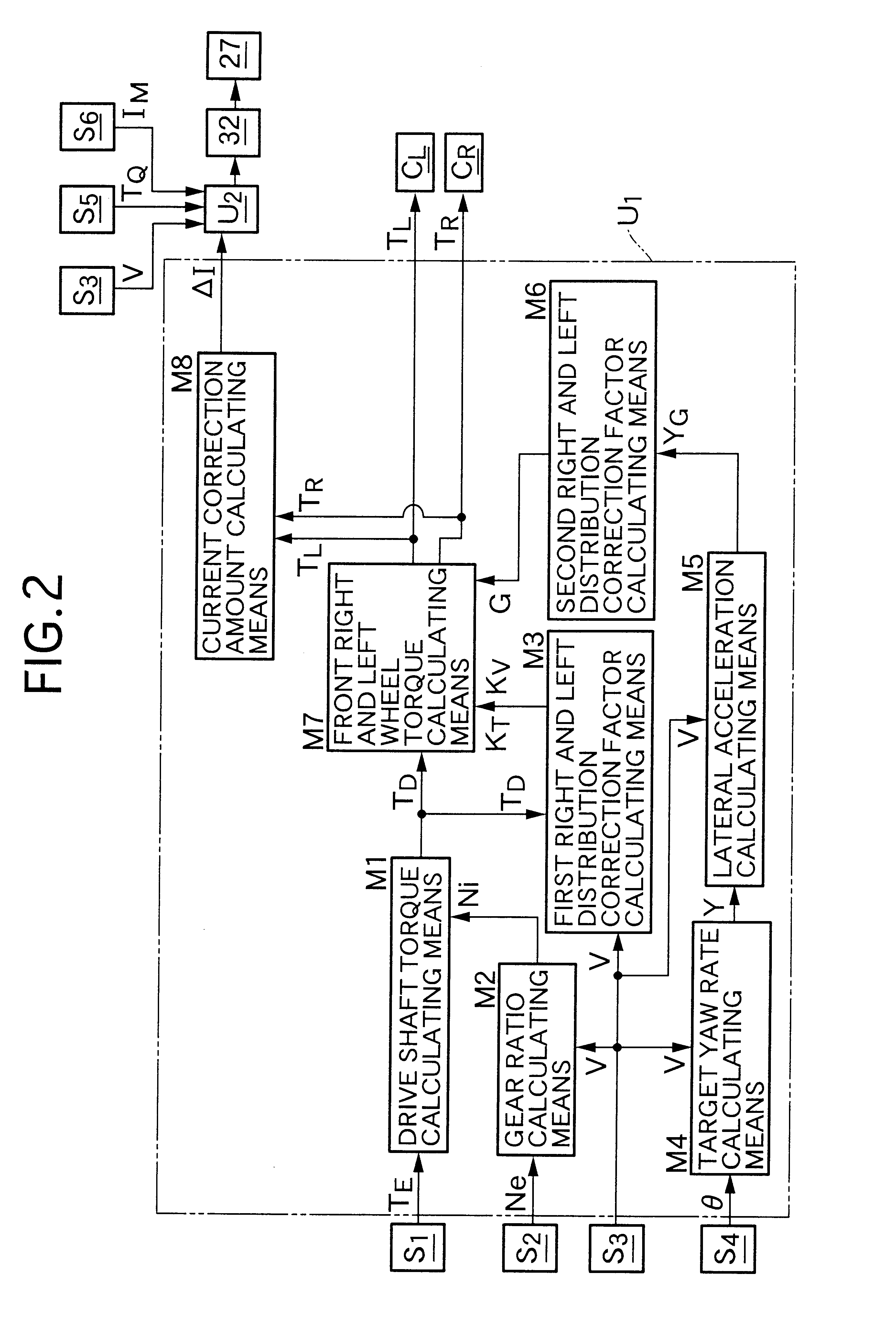
As shown in FIG. 1, a transmission M is connected to the right end of an engine E which is laterally mounted in the front part of the vehicle body of a front-engine front-wheel drive vehicle, and a driving force distribution device T is placed to the rear of engine E and transmission M. A front right wheel W.sub.FR and a front left wheel W.sub.FL are connected to a right drive shaft A.sub.R and a left drive shaft A.sub.L, respectively, which extend laterally from the right end and the left end of the driving force distribution device T.

The driving force distribution device T comprises a differential D to which the driving force is transmitted from an outer toothed gear 3 meshing with an input gear Z provided on an input shaft 1 extending from the transmission M. The differential D employs a double pinion type planetary gear mechanism and comprises a ring gear 4 which is integrally formed with the above-mentioned outer toothed gear 3, a sun gear 5 which is provided coaxially inside t...


PUM


Abstract

A co-operative control system for a vehicle including a force distribution device for distributing the driving force or braking force between the right and left wheels or between the front and rear wheels, includes a first control means for controlling the operation of the force distribution device, an electric power steering device, having a motor for applying a steering assist torque to a vehicle steering system, and a second control means for calculating a motor control signal for driving the motor. The motor control signal is based on at least the steering torque detected by a steering torque detecting means. The first control means calculates a correction signal for correcting said motor control signal based on the distributed force generated by the force distribution device, the second control means drives the motor based on the corrected motor control signal obtained by correcting the motor control signal with the correction signal and the first control means stops the operation of the force distribution device when the electric power steering device or the second control means malfunctions.

Description

The present application claims priority under 35 U.S.C. 119 of Japanese laid-open patent application serial no. 11-253033, filed Sep. 9, 1999, the disclosure of which is incorporated herein by reference.1. Field of the InventionThe present invention relates to co-operative control systems for vehicles comprising a combination of a force distribution device, which distributes the driving force or braking force between the right and left wheels or between the front and rear wheels, and an electric power steering device that applies a steering assist torque to a steering system.2. Description of the Relevant ArtThere is a known technique for enhancing turning performance of a vehicle, where the ratio by which the engine driving force is distributed between the right and left driven wheels is made variable, and the driving force distributed to the outer turning wheel is increased while the driving force distributed to the inner turning wheel is decreased so as to generate a yaw moment i...

Claims


Application Information

Patent Timeline
IPC IPC(8): B60K17/16B62D9/00B62D5/04B62D11/18B62D11/06B62D6/00B60K17/34B60K23/04B60W10/00B60W10/02B60W10/08B60W10/119B60W10/12B60W10/18B60W10/184B60W10/20B60W50/02B62D119/00B62D121/00F16H48/10F16H48/11F16H48/20F16H48/36F16H48/38H02P29/00
CPCB60K17/16B62D5/0472B62D9/002B62D5/0484F16H48/10
Inventor SHINMURA, TOMOYUKIINAGAKI, HIROMIHORI, MASAKATSUTOMARI, TATSUHIROOKUMA, SHINJIIWAZAKI, AKIHIROKURIBAYASHI, TAKASHIWADA, KAZUHIRO
Owner HONDA MOTOR CO LTD
Learn More