Multi-valve injection/aspiration manifold

a manifold and multi-valve technology, applied in the field of ports, can solve the problems of large dead spaces in the ports, general uneven flow characteristics, and easy formation of air pockets

Inactive Publication Date: 2002-04-02
CAREFUSION 303 INC +1
View PDF12 Cites 94 Cited by
  • Summary
  • Abstract
  • Description
  • Claims
  • Application Information

AI Technical Summary

Problems solved by technology

The flow channel through the manifold has also had this elongate wide configuration, and consequently, has been susceptible to the formation of air pockets and to generally uneven flow characteristics.
In this case, the flow channel has reamined separate and the problems with dead spaces in the ports have been significant.
These seals have not been capable of withstanding high pressure such as those sometimes associated with an injection into an adjacent port.
The resulting high back pressure has sometimes caused the valve element to deform and lodge in the lumen of the port, rendering the port inoperative.
In many of these cases, damage to the injection port has resulted.

Method used


Image

  • Multi-valve injection/aspiration manifold
  • Multi-valve injection/aspiration manifold
  • Multi-valve injection/aspiration manifold

Examples


Embodiment Construction

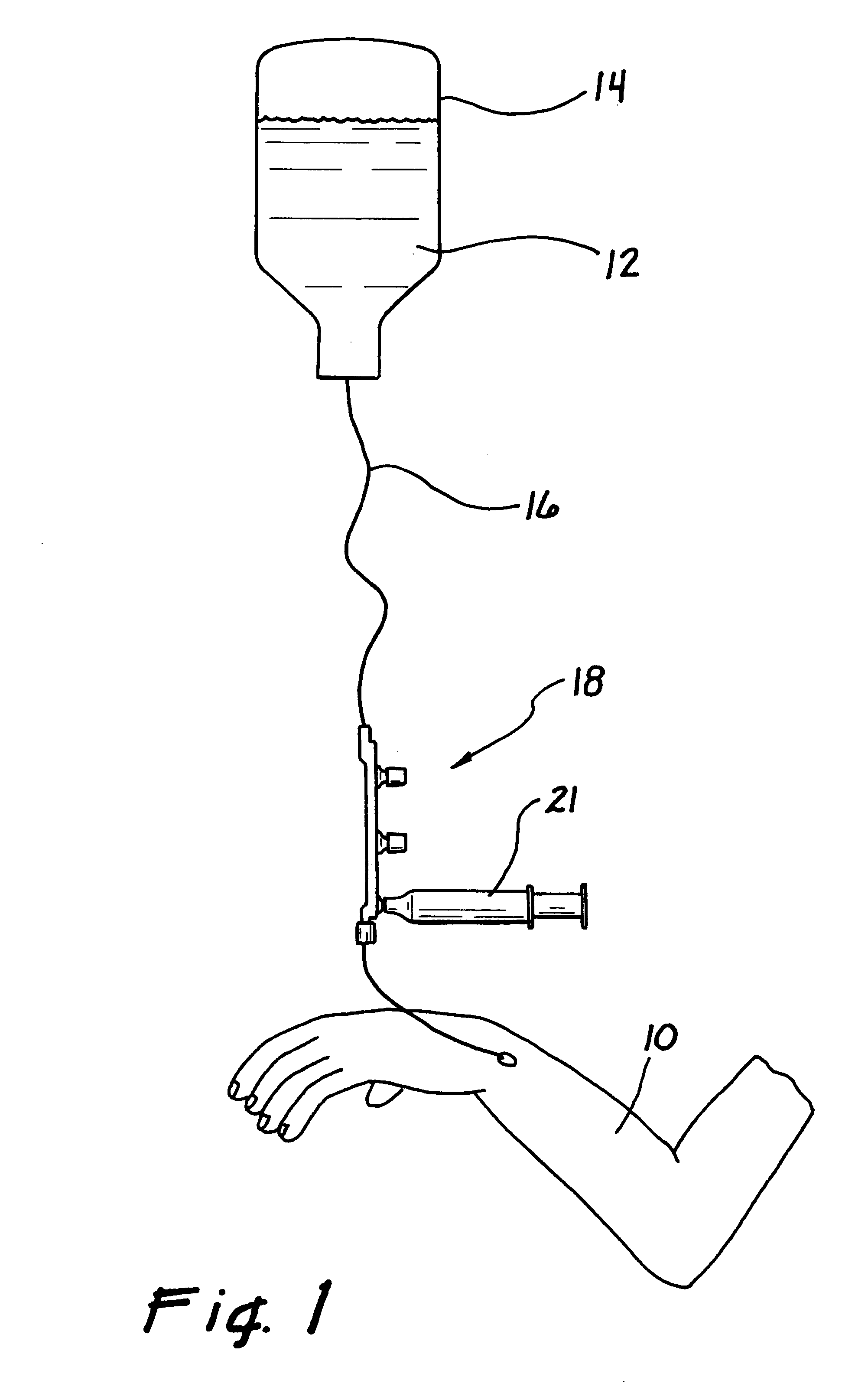
The arm and hand of a patient are illustrated in FIG. 1 and designated generally by the reference numeral 10. An IV solution 12 contained in a reservoir, such as a bottle or bag 14, is appropriately communicated to the patient 10 through an IV line 16. An injection manifold 18 of the present invention is connected in series with the line 16 and provides a site where drugs and other fluids can be injected, typically through a syringe 21, into the IV solution in the line 16.

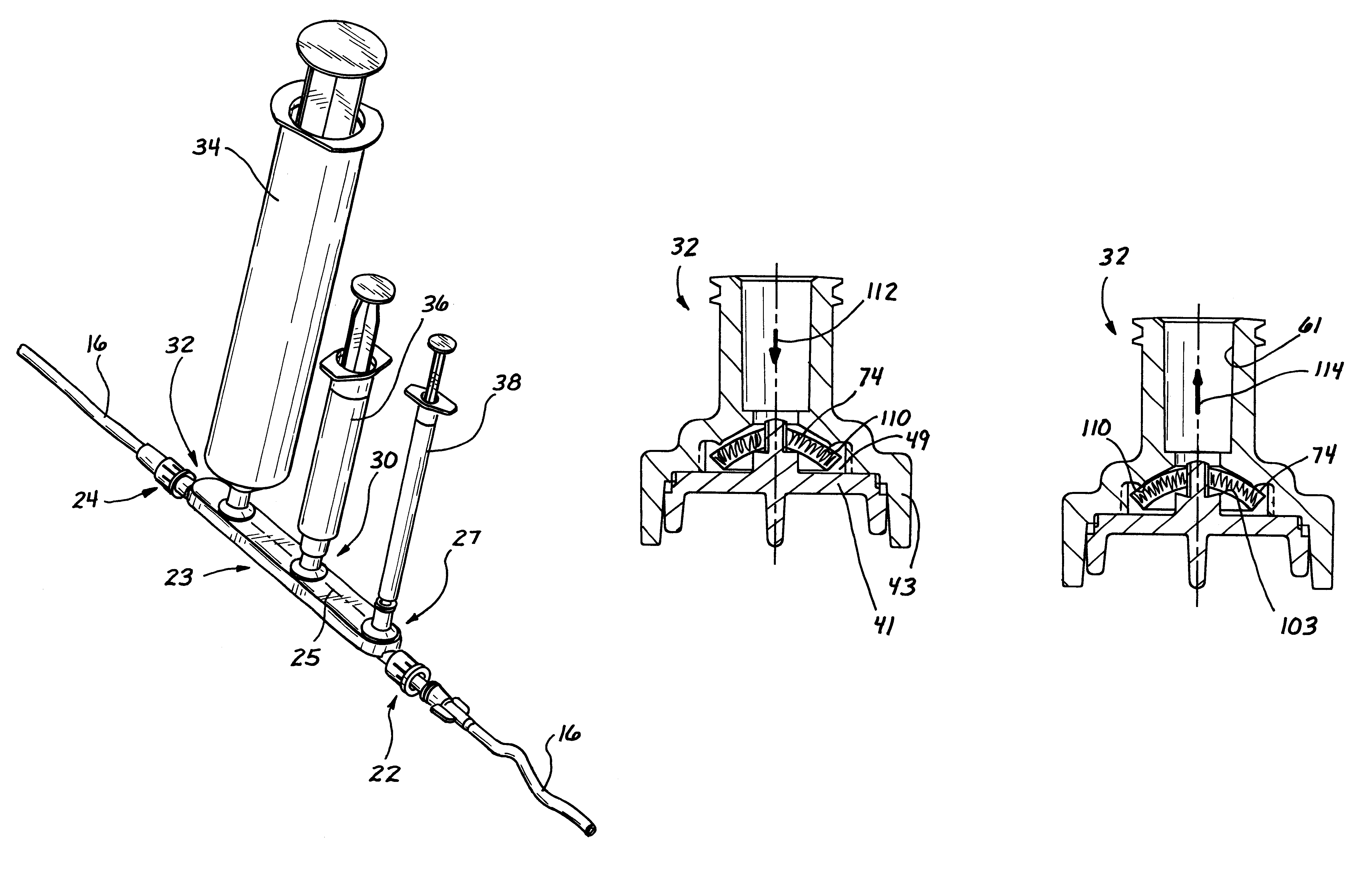
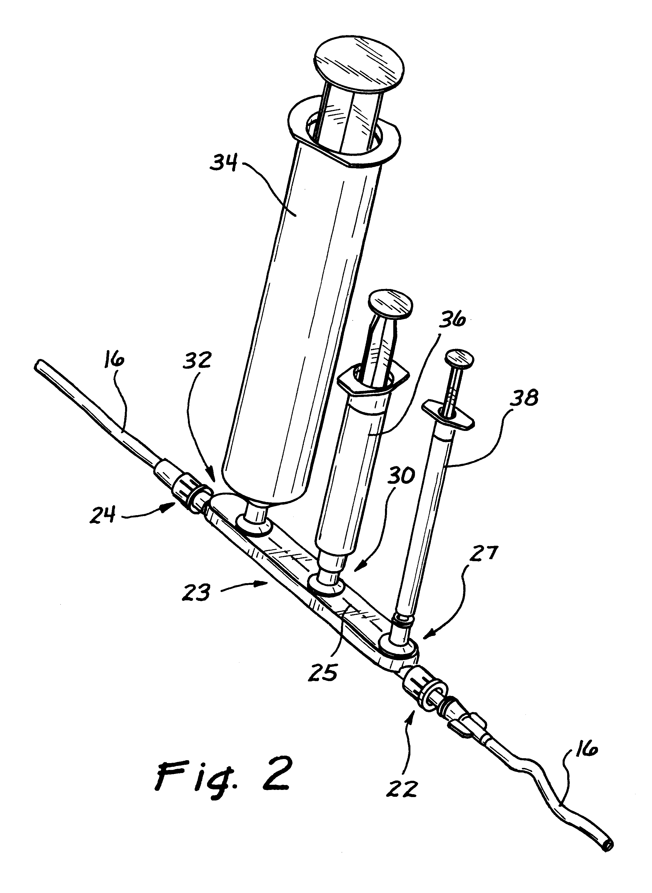
The manifold 18 of a preferred embodiment is illustrated in greater detail in FIG. 2. In this view it can be seen that the manifold 18 has a housing 23 with an elongate configuration, and extends generally along an axis 25. The housing 23 is connected in series with the IV line 16, for example by a pair of connectors 22 and 24, so that the flow channel and the IV line 16 also extends through the housing 23.

A plurality of injection ports 27, 30 and 32 can be molded integrally with the housing 23 and spaced along the...


PUM


Abstract

An IV manifold includes a plurality of injection/aspiration ports and has an elongate configuration with a width greater than the diameter of the ports. A flow channel is formed between mating members of a housing and provided with a U-shaped configuration. Projections along the flow channel direct fluid flow into valve cavities associated with the ports to clear dead spots around the valve elements. A check valve included in the manifold tends to direct high pressures against the valve elements which respond by forming surface seals thereby avoiding deformation. An aspiration port can be formed with a second seal disposed on the side of the valve element opposite the first seal. Opening this second seal by negative pressure in the lumen of the port provides for the aspiration of fluids in the flow channel. Two-way aspiration can be provided by a valve having a cage with or without compressible characteristics to accommodate low tolerance fittings.

Description

1. Field of the InventionThis invention relates generally to ports for injecting fluids into an intravenous (IV) line, and more specifically to injection manifolds including multiple injection ports.2. Discussion of the Prior ArtPatients are commonly injected with IV solutions which are initially provided in a bottle or bag and dripped into the vein of the patient through an IV line. Typically an injection port is provided along the line and adapted to function with a syringe to permit an injectate to be added to the IV solution. If a large quantity of injectate, or multiple injectates, are to be added to the IV solution, multiple ports may be required. In such a case, an injection manifold can be disposed in the IV line to provide multiple injectate ports.A check valve is also commonly included in the IV line where it is disposed upstream from the injection manifold. It is the purpose of the check valve to permit fluid flow only in the direction of the patient. This ensures that th...

Claims


Application Information

Patent Timeline
Patent Type & Authority Patents(United States)
IPC IPC(8): A61M39/24A61M5/14A61M39/02A61M39/00
CPCA61M5/1408A61M39/02A61M39/24A61M2039/2466A61M2039/242A61M2039/2433A61M2039/0202Y10T137/7843
Inventor FEITH, RAYMOND P.TRUITT, TIMWERSCHMIDT, GARY S.
Owner CAREFUSION 303 INC
Why Eureka
Try Eureka