Cleaning appliance

a cleaning appliance and cleaning technology, applied in the field of cleaning appliances, can solve the problems of affecting the performance of other cleaning appliances, and achieve the effect of efficient liquid removal

Inactive Publication Date: 2002-04-16
BURNS GEORGE M
View PDF18 Cites 40 Cited by
  • Summary
  • Abstract
  • Description
  • Claims
  • Application Information

AI Technical Summary

Benefits of technology

Therefore, there existed a need to provide a hard surface cleaning appliance that would supply cleaning liquid to a surface to

Problems solved by technology

The Roden appliance is an advancement in the area of hard surface cleaning appliances, but the arrangement of the

Method used


Image

  • Cleaning appliance
  • Cleaning appliance
  • Cleaning appliance

Examples


Embodiment Construction

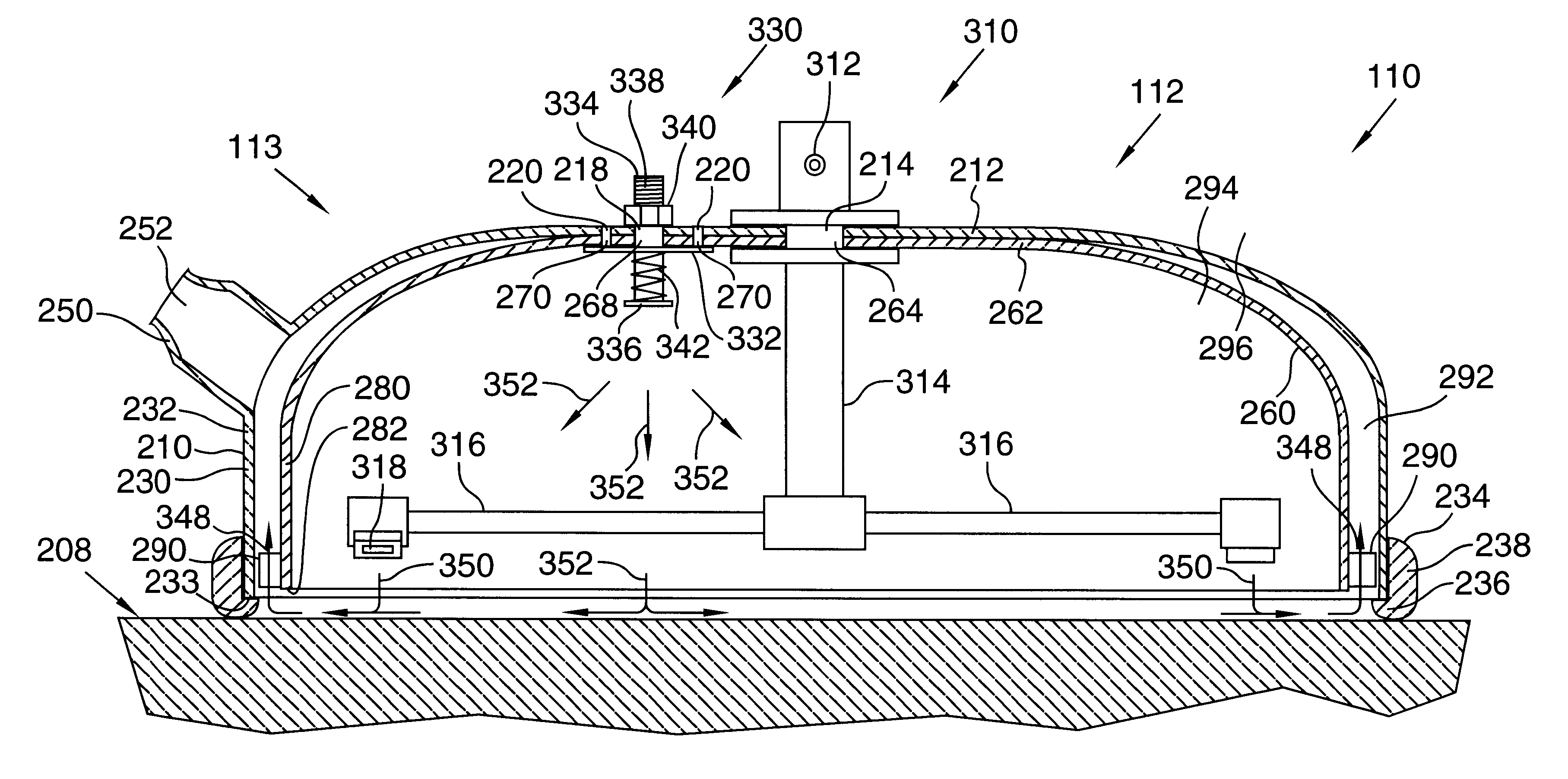
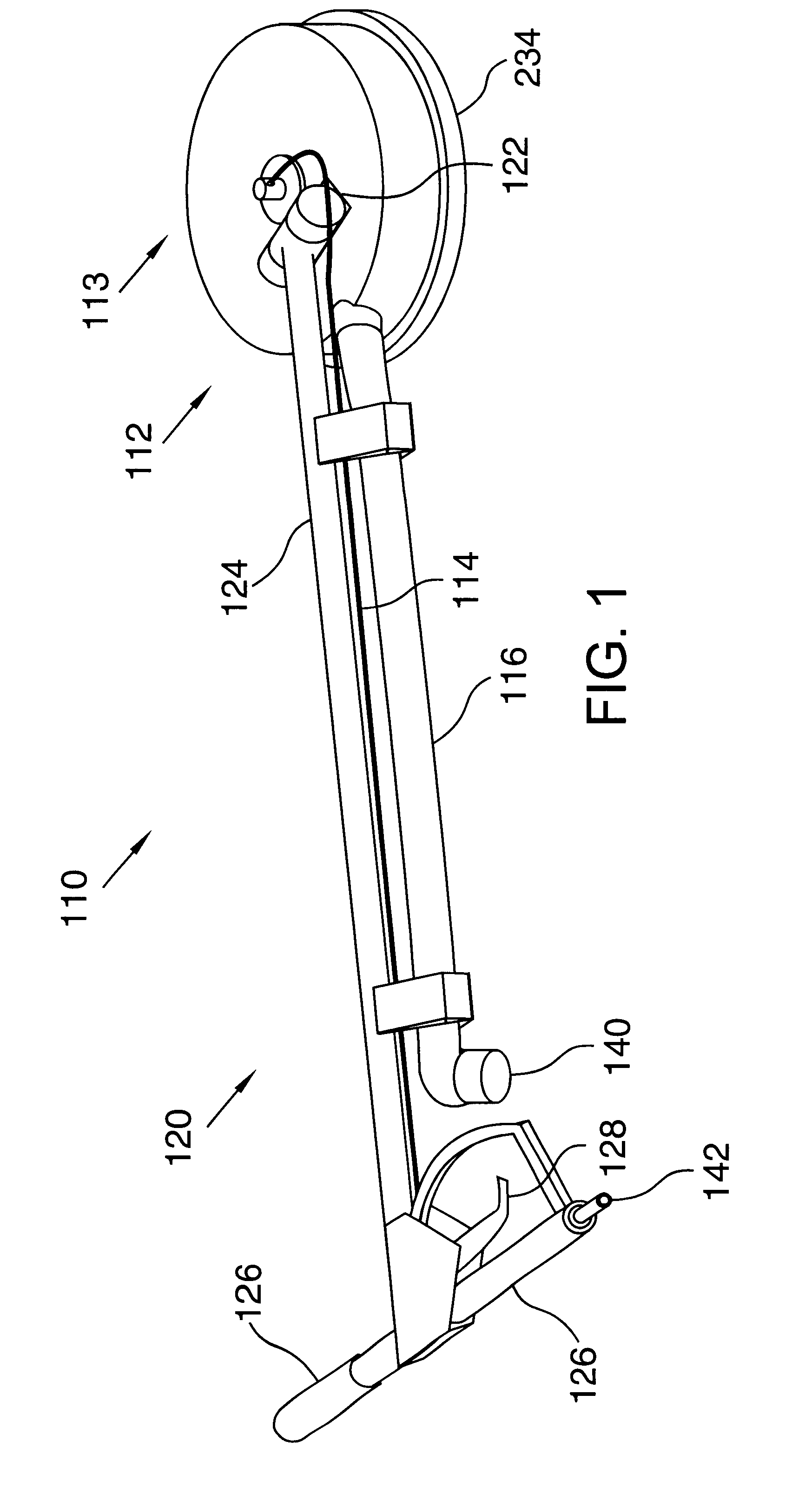
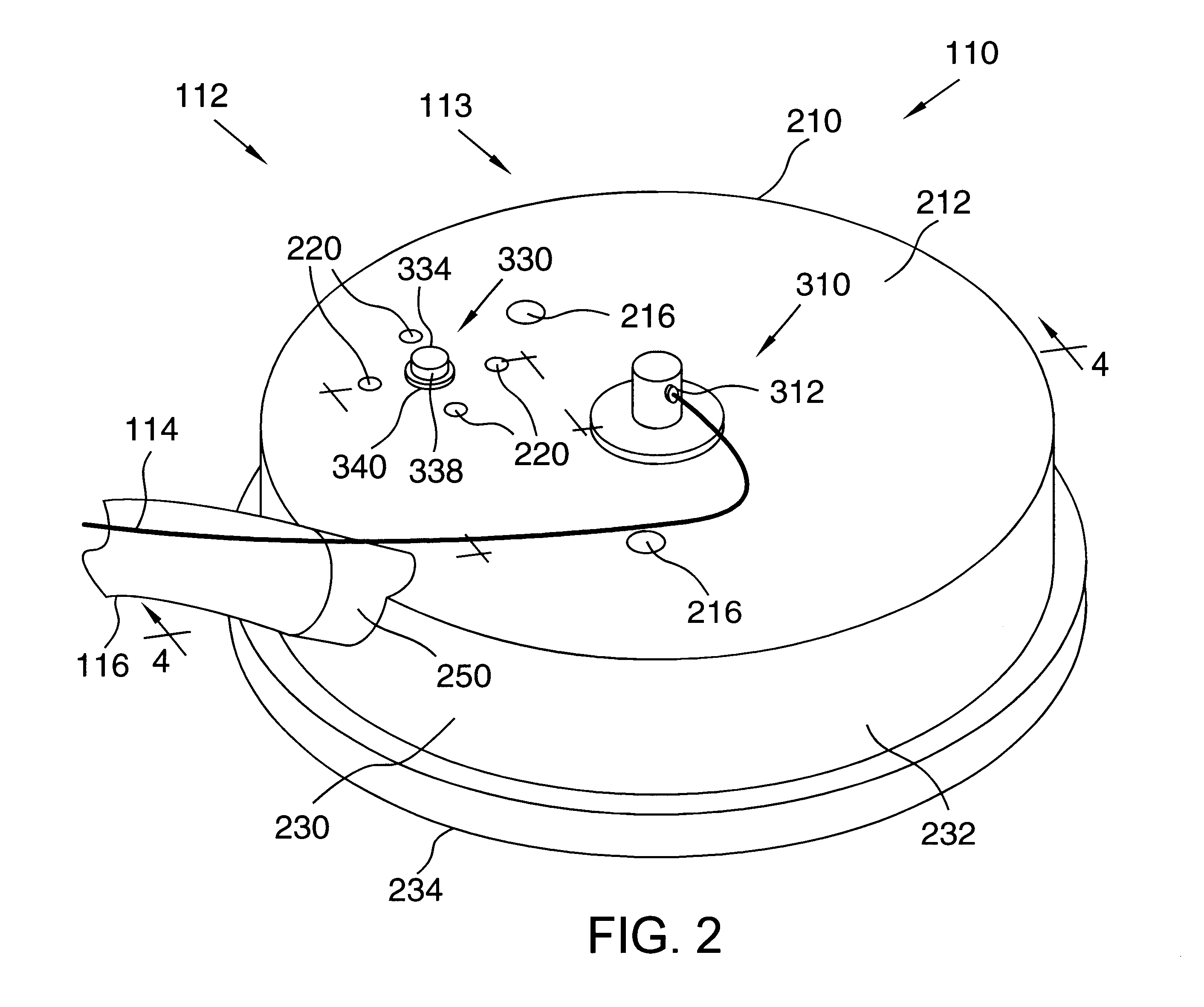
Referring to FIG. 1, cleaning appliance 110 includes a cleaning head 112. Cleaning head 112 includes a hood 113. A cleaning liquid supply line 114 and a vacuum supply line 116 communicate with hood 113, and a handle 120 is pivotally attached to hood 113 with brackets 122. Preferably the pivotal attachment includes bearings to aid in pivotal movement of handle 120 relative to hood 113. Brackets 122 are preferably secured to hood 113 by bolts, but they may be secured in some other manner. A shaft 124 of handle 120 extends from the pivotal attachment and supports cleaning liquid supply line 114 and vacuum supply line 116, which run substantially parallel to shaft 124. Handgrips 126 preferably extend transversely in opposing directions from an end of shaft 124 distal from cleaning head 112. A trigger lever 128 actuates a valve to allow cleaning liquid to flow to cleaning head 112 or to prevent cleaning liquid from flowing to cleaning head 112. Vacuum supply line 116 preferably terminate...


PUM


Abstract

A hard surface cleaning appliance includes a hood separating an interior space within the hood from an exterior space outside the hood. The hood includes a top wall as well as a solid outer side wall and an inner side wall depending from the top wall. The outer side wall includes a lower edge that is adapted to contact a surface to be cleaned, while the inner side wall includes a lower edge spaced inwardly of the outer wall that is elevated above the surface to be cleaned. A vacuum passage is formed between the inner side wall and the outer side wall, and a vacuum source is fluidly connected to the vacuum passage. A spout within the interior space is fluidly connected to a cleaning liquid source. The appliance may include a vacuum relief passage extending through the hood and thereby fluidly connecting the interior space with the exterior space. A vacuum relief valve can prevent fluids from exiting the interior space through the vacuum relief passage, but allow fluids to enter the interior space through the vacuum relief passage. Also, the outer wall may include a solid outer depending side wall and a solid skirt mounted on a lower edge of the outer depending side wall, the skirt adapted to contact the surface to be cleaned.

Description

1. Technical FieldThis invention generally relates to a cleaning appliance, and more specifically relates to a hard surface cleaning appliance.2. Background ArtMany appliances have been devised for cleaning hard surfaces. Some such appliances have included spray nozzles that spray high pressure liquid on the surface to be cleaned. Regulations require that such appliances also remove the liquid and accompanying dirt (i.e., soil and / or other contaminants) from the surface after it has been sprayed.One example of an appliance for spraying liquid on a surface is disclosed in U.S. Pat. No. 5,711,051 to Roden issued on Jan. 27, 1998 (hereinafter Roden). The Roden appliance includes a hood and an inner shroud positioned internally of the hood. Vacuum passages are formed between the hood and the shroud. A foramenous skirt depends from the lower edge of the hood and rests on the surface to be cleaned. The skirt is foramenous to allow air to be drawn through it and into the vacuum passage. A ...

Claims


Application Information

Patent Timeline
IPC IPC(8): A47L11/20A47L11/00
CPCA47L11/201A47L11/4088A47L11/4044B08B3/024B08B2203/0229
Inventor BURNS, GEORGE M.
Owner BURNS GEORGE M
Why Eureka
Try Eureka