Pseudo-monolithic laser with an intracavity optical parametric oscillator

a pseudo-monolithic laser and optical parametric oscillator technology, applied in the direction of laser details, active medium materials, optical resonator shape and construction, etc., can solve the problems of increasing the size of laser devices and exacerbate the many fabrication problems of these devices

Inactive Publication Date: 2002-04-16
UNITED STATES OF AMERICA THE AS REPRESENTED BY THE SEC OF THE ARMY
View PDF3 Cites 43 Cited by
  • Summary
  • Abstract
  • Description
  • Claims
  • Application Information

AI Technical Summary

Problems solved by technology

The need for increasingly smaller laser devices has onl...

Method used


Image

  • Pseudo-monolithic laser with an intracavity optical parametric oscillator
  • Pseudo-monolithic laser with an intracavity optical parametric oscillator
  • Pseudo-monolithic laser with an intracavity optical parametric oscillator

Examples


Embodiment Construction

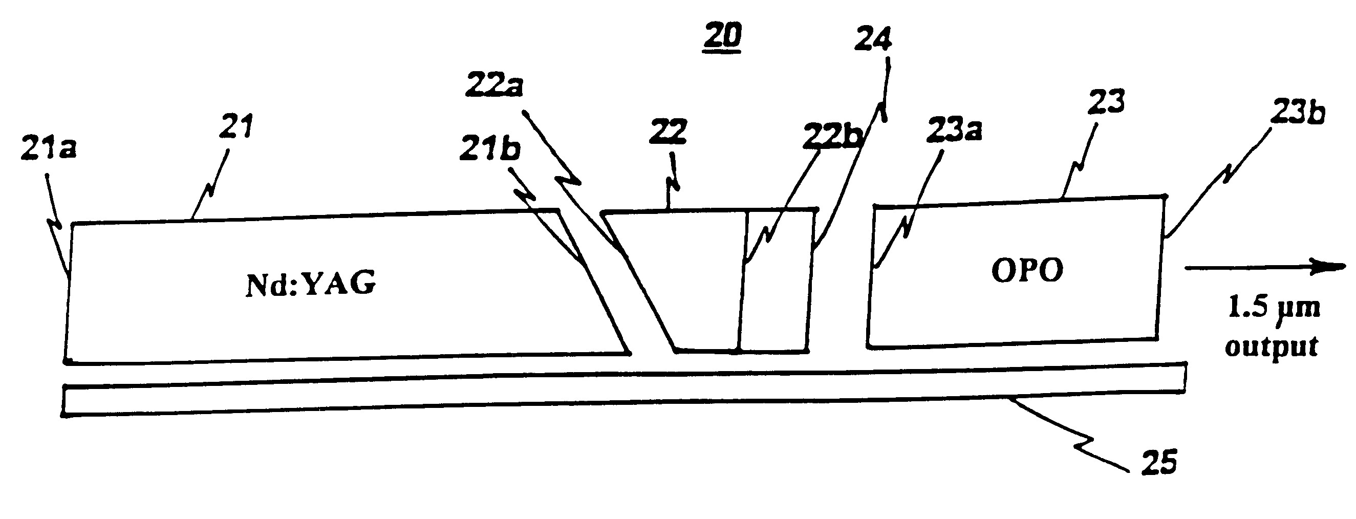
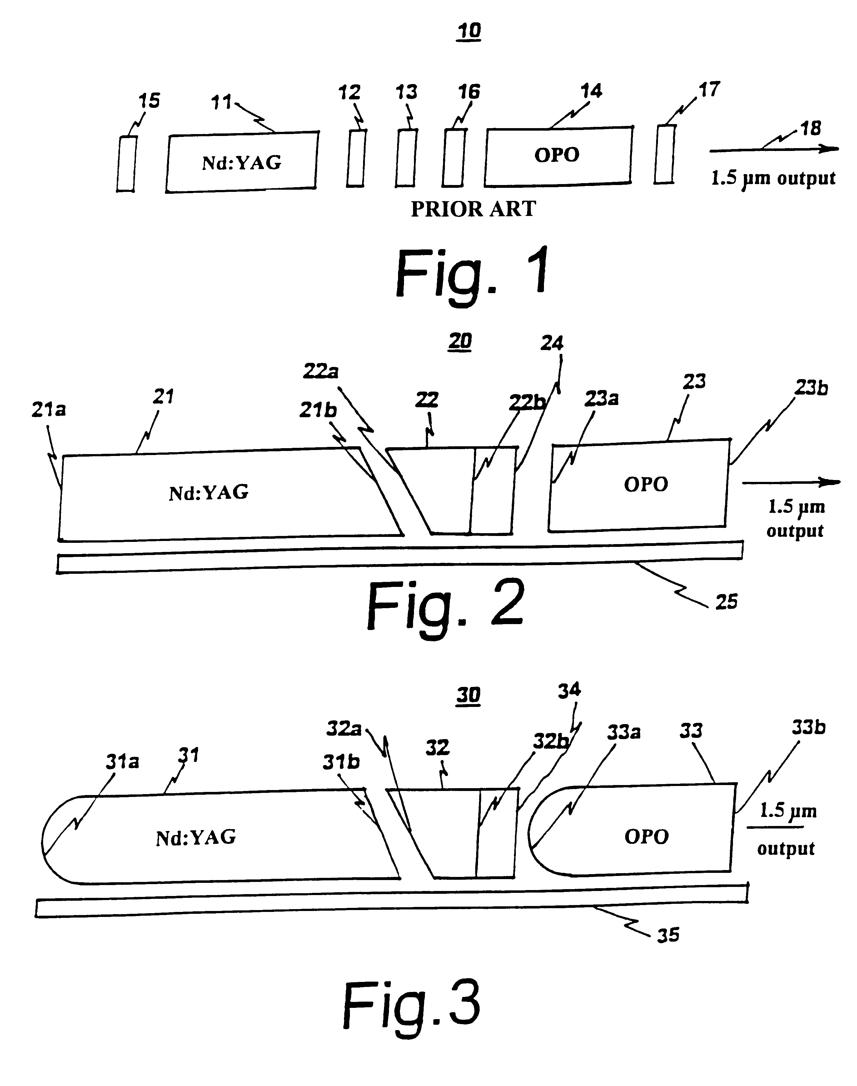
FIG. 1 shows a laser subassembly, which lacks only an optical pump. Although any number of designs exist for an optically pumped, passively Q-switched, 1.5 micron wavelength, laser; the typical model 10 shown using an optical parametric oscillator (OPO) for frequency shifting has been chosen for improvement. The subassembly contains many discrete optical elements i.e. a laser rod of gain material 11, a polarizing element 12, a passive Q-switch 13, a body or rod of nonlinear dielectric material 14 for the OPO and three mirrors or reflecting filters 15, 16 and 17. All of these elements normally share a straight common optical axis 18. Moving from left to right along this axis, the first mirror 15 is called an HR mirror, because it is highly reflective at the pump-laser wavelength, in this case 1.06 microns. The next element, the gain material 11, may be a rod shaped body of a specific solid state laser crystal, such as the material Neodymium:Yttrium-Aluminum-Garnet (Nd:YAG). These cry...


PUM


Abstract

A subassembly for a high powered light pumped, Q-switched and linearly polarized laser with an optical parametric oscillator, the subassembly consisting of two or three rod shaped elements having precisely ground endfaces with selected coatings mounted on a special pallet that at least partially aligns the optical axes of the elements.

Description

1. Field of the InventionThe present invention generally relates to light pumped lasers, q-switched lasers, nonlinear optical elements, optical frequency conversion by nonlinear processes and micro-lasers. More particularly it relates to lasers in the near infrared spectrum extensively used for invisible sensing and range finding.2. Description of Prior ArtUntil now, a device with the same functionality as this invention would consist of many discrete optical components, each with associated optical mounts. Traditionally, these devices require constant precise mechanical alignment for optimized resonator functionality. The need for increasingly smaller laser devices has only exacerbated the many fabrication problems of these devices.A very sophisticated small optically pumped laser subassembly is provided that consists of a minimum number of specially shaped and coated precision parts that are easily assembled and permanently adjusted in a very short time.The foregoing and other obj...

Claims


Application Information

Patent Timeline
IPC IPC(8): H01S3/108H01S3/081H01S3/082H01S3/16H01S3/11
CPCH01S3/1083H01S3/025H01S3/0606H01S3/061H01S3/0615H01S3/1643H01S3/082H01S3/113H01S3/0621
Inventor NETTLETON, JOHN E.SCHILLING, BRADLEY W.BARR, DALLAS N.
Owner UNITED STATES OF AMERICA THE AS REPRESENTED BY THE SEC OF THE ARMY
Why Eureka
Try Eureka