Method of controlling the AC pulsed arc welding and welding power supply apparatus therefor

a pulsed arc welding and control method technology, applied in the direction of arc welding apparatus, welding equipment, manufacturing tools, etc., can solve the problems of insufficient weld penetration, insufficient penetration, and frequent interruption of arcs

Inactive Publication Date: 2002-04-23
DAIHEN CORP
View PDF3 Cites 45 Cited by
  • Summary
  • Abstract
  • Description
  • Claims
  • Application Information

AI Technical Summary

Problems solved by technology

In the case of the thin plate to be welded, an excessively large heat input to the workpiece tends to result in a burn-through and an excessively small heat input to the workpiece tends to result in an incomplete penetration, whichever is a weld defect.
In the event that the re-igniting voltage Vrs is not applied or is too low at the time of the polarity switching, the arc will no longer be re-ignited during the duration of the EN polarity and an arc interruption may therefore result in.
However, depending on the material used for the workpiece to be welded, the presence or absence of an oxide film on a surface of the workpiece to be welded, the type of a shield gas used, the gas shielded condition and others, an arc interruption often occur a few milliseconds to a few hundreds milliseconds subsequent to the re-ignition of the arcing at the time of polarity switching.
Once this arc interruption occurs during the course of welding, weld defects such as, for example, aesthetically poor weld beads, insufficient weld penetration, deposition of relatively large spatters and others will result in.
This shift of the negative point proceeds with passage of time and, therefore, the arc is correspondingly elongated and, finally at the timing t6, the arc can no longer be maintained, resulting in the arc interruption.
As hereinbefore discussed, once the arc interruption occurs, weld defects such as, for example, aesthetically poor weld beads, insufficient weld penetration, deposition of relatively large spatters and others will result in.

Method used


Image

  • Method of controlling the AC pulsed arc welding and welding power supply apparatus therefor
  • Method of controlling the AC pulsed arc welding and welding power supply apparatus therefor
  • Method of controlling the AC pulsed arc welding and welding power supply apparatus therefor

Examples


embodiment 1

[Embodiment 1]

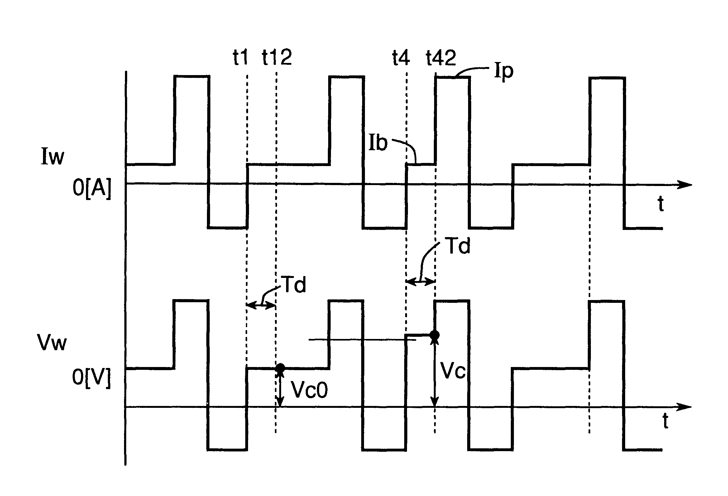
Referring now to FIG. 9, there is shown a chart showing changes in welding current and voltage with time occurring during the performance of an AC pulsed arc welding according to the first embodiment of the present invention in which the first arc interruption preventing method is employed. In this figure, at the timing t42, in the event of Vc.gtoreq.Vc0+.DELTA.Vc determined by the first arc interruption preventing method described with reference to FIG. 8, a predetermined arc interruption preventive current Ic of a value higher than the base current Ib is supplied. As a result of the supply of this arc interruption preventive current Ic, the arc is pulled to a normal course with its longitudinal axis aligned with a direction of feed of the welding wire the negative point by the reason as will be described subsequently with reference to FIG. 10 and the negative point once formed at a distant location is newly formed at a location immediately beneath the welding wire. A...

embodiment 2

[Embodiment 2]

FIG. 14 illustrates a chart showing changes in welding current and voltage with time occurring during the performance of an AC pulsed arc welding according to the second embodiment of the present invention in which the first arc interruption preventing method is employed.

In this figure, at the timing t42, in the event of Vc.gtoreq.Vc0+.DELTA.Vc determined by the first arc interruption preventing method described with reference to FIG. 8, the peak current Ip which is a value higher than the base current Ib flows. The timing at which the peak current Ip is supplied is determined by the Tb control based on the previously discussed equation (1), but when the arc interruption is anticipatorily detected, the peak current Ip is forcibly supplied regardless of the Tb control. Since once the peak current Ip is supplied, the arc rigidity increases as described hereinbefore with the arc consequently pulled towards the normal course, the negative point is newly formed at a locatio...

embodiment 3

[Embodiment 3]

Referring to FIG. 16, there is shown a chart showing changes in welding current and voltage with time occurring during the performance of an AC pulsed arc welding according to the third embodiment of the present invention in which the second arc interruption preventing method is employed. In this figure, at a timing a detection wait time Td after the timing t4, based on the second arc interruption preventing method described previously with reference to FIG. 8 the base voltage increase rate dVb / dt is detected from time to time and, then, a decision is made to determine if the detected value of the base voltage increase rate is larger than the predetermined base voltage increase rate determining value .DELTA.Vu. At the timing 43, if a result of the decision indicates "YES", the arc interruption preventive current Ic of a value higher than the base current Ib is supplied. As the arc interruption preventive current Ic is supplied, the arc rigidity increases as described h...


PUM

PropertyMeasurementUnit
re-igniting voltage Vrsaaaaaaaaaa
diameteraaaaaaaaaa
polarityaaaaaaaaaa

Abstract

An consumable electrode AC pulsed arc welding is performed by repeatedly executing a cycle of supplying a peak current Ip in an electrode positive polarity, then supplying an electrode negative current Ien in an electrode negative polarity and finally supplying a base current Ib in the electrode positive polarity. During a base current supply time, the rate of increase dVb / dt of the base voltage Vb is detected. Should the base voltage increase rate dVb / dt detected be larger than a predetermined determining value DELTAVu, it means that the arc interruption is likely to occur and, therefore, since that timing, the peak current Ip for the subsequent cycle is supplied to thereby prevent the arc interruption from occurring.

Description

1. Field of the InventionThe present invention generally relates to the art of AC pulsed arc welding utilizing a consumable electrode and, more particularly to a method of controlling the consumable electrode AC pulsed arc welding and a welding power supply apparatus therefor, which are effective to avoid an arc interruption, which is apt to occur upon re-ignition subsequent to polarity switching of the electrode, thereby to provide a high weld quality in a workpiece to be welded.2. Description of the Prior ArtThe AC pulsed arc welding is well known in the art and is a process wherein, while a welding wire is supplied at a predetermined feed speed, a first arc generating interval with the welding wire held at a positive polarity (which interval is hereinafter referred to as an "EP (electrode-positive) arcing interval") wherein an arc is generated between the welding wire and the workpiece to be welded that are then polarized to positive and negative poles, respectively, and a second...

Claims


Application Information

Patent Timeline
Patent Type & Authority Patents(United States)
IPC IPC(8): B23K9/08B23K9/09B23K9/073B23K9/173B23K9/095
CPCB23K9/08B23K9/093B23K9/092B23K9/091
Inventor TONG, HONJYUNUEYAMA, TOMOYUKITAKAHASHI, NORIHITOSHIOZAKI, HIDEOMONDORI, HIROYASU
Owner DAIHEN CORP
Why Eureka
Try Eureka