Warning light synchronization

a technology of synchronizing warning lights and synchronizing lights, which is applied in the direction of lighting applications, lighting and heating apparatus, and with built-in power, etc., can solve the problems of inability to obtain control apparatuses and methods for accomplishing such synchronization

Inactive Publication Date: 2002-04-23
WHELEN ENGINEERING COMPANY
View PDF2 Cites 29 Cited by
  • Summary
  • Abstract
  • Description
  • Claims
  • Application Information

AI Technical Summary

Problems solved by technology

Control apparatus and methods for accomplishing such emulation have not previously been available.

Method used


Image

  • Warning light synchronization
  • Warning light synchronization
  • Warning light synchronization

Examples


Embodiment Construction

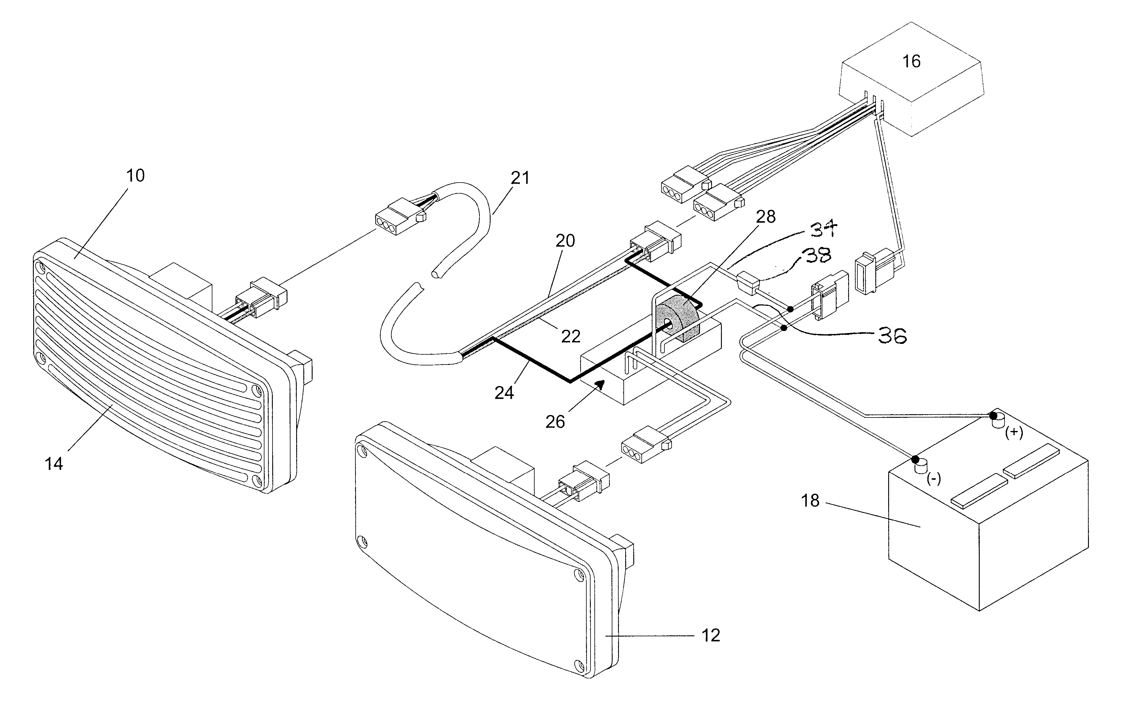
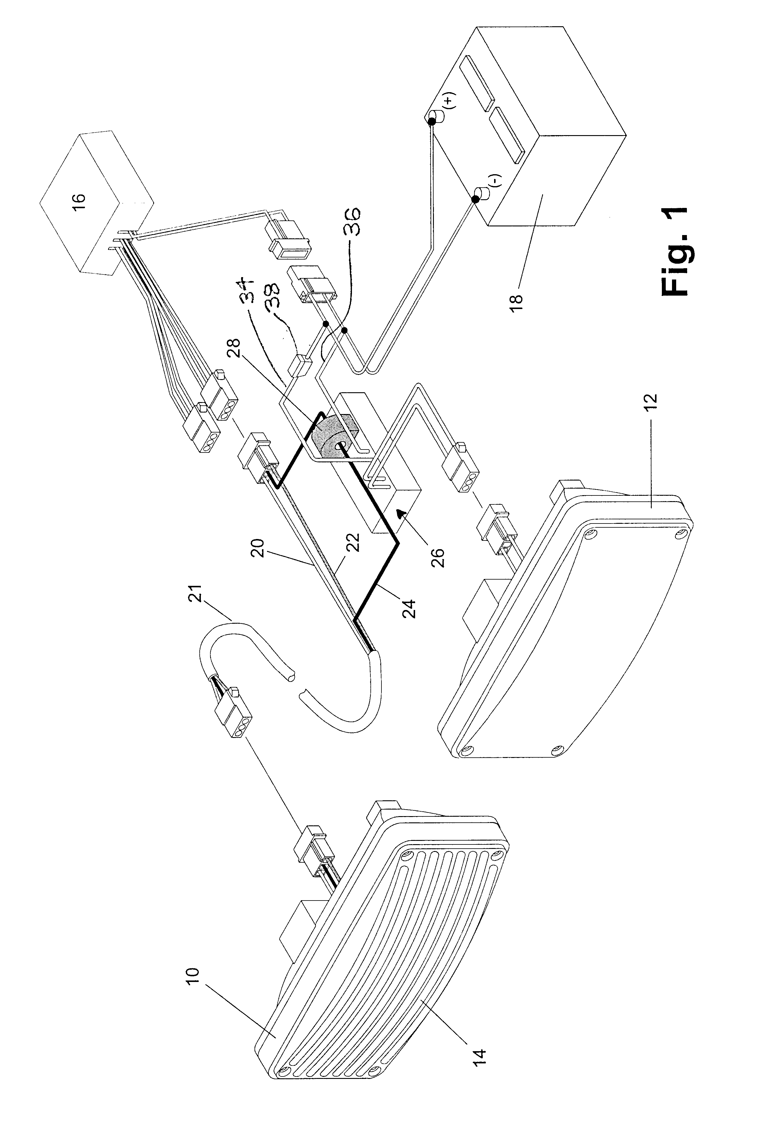
FIG. 1 represents utilization of the present invention to synchronize the operation of a pair of adjacently mounted lightheads. Thus, FIG. 1 depicts a strobe lighthead 10 and an auxiliary lighthead 12. The strobe lighthead will typically comprise a linear flash tube having an anode, a cathode and a trigger electrode. The flash tube will be positioned on the linear focal point of a parabolic trough reflector and the generated light will be focused into a high intensity band by the reflector. The strobe lighthead 10, in the disclosed embodiment, also includes a lens 14 which is provided with optics which further shape the generated light into a desired radiation pattern. Energization of strobe lighthead 10 is controlled by a strobe power supply 16. The power supply 16 will, in the typical vehicular operating environment, be connected to a low voltage direct current source, i.e., the vehicle's battery 18. Strobe power supply 16 will have the capability of producing pulse trains which a...


PUM


Abstract

The gating of energizing current flow to a relatively low intensity light source is controlled by monitoring the flow of energizing current to an associated strobe light. The controller produces gating control pulses which lead the strobe energization signals to thereby cause the strobe generated light to be superimposed on light from the low intensity source.

Description

1. Field of the InventionThe present invention relates to the exercise of control over a strobe light and one or more switched direct current supplies and, particularly, to synchronizing the energization of a high intensity directional light and a comparatively low intensity light which illuminates a zone. More specifically, the present invention is directed to a control for plural warning lights and, especially, to apparatus which achieves the sequential energization of a relatively low intensity light source and a spatially separated high intensity light source. Accordingly, the general objects of the present invention are to provide novel and improved methods and apparatus of such character.2. Description of the Prior ArtIt has been found that, under certain operating conditions, the visibility of a warning light system may be enhanced by causing energization of a high intensity warning light, namely a strobe which employs a gaseous discharge tube, subsequent to, but during, the ...

Claims


Application Information

Patent Timeline
Patent Type & Authority Patents(United States)
IPC IPC(8): B60Q1/46B60Q1/26
CPCB60Q1/46B60Q2900/10
Inventor OLSON, JOHN F.
Owner WHELEN ENGINEERING COMPANY
Why Eureka
Try Eureka