Optical fiber holder

a technology of optical fiber and holder, applied in the field of optical fiber holder, can solve the problems of inability to accurately measure the diameter of the holder, and achieve the effects of reliable holding, easy deformation of small projection, and no deformation of transmission characteristics

Inactive Publication Date: 2002-04-23
SUMITOMO ELECTRIC IND LTD
View PDF5 Cites 38 Cited by
  • Summary
  • Abstract
  • Description
  • Claims
  • Application Information

AI Technical Summary

Benefits of technology

With the optical fiber holder according to the present invention, even if the plurality of optical fibers which are arranged parallel to each other or face to face have a diameter error, when the lid member presses the optical fibers against the bottom portion of the positioning groove, the small projections formed on the lid member or positioning groove which comes into contact with the optical fibers deform in accordance with the diameters of the optical fibers. Consequently, each one of the plurality of optical fibers is pressed and reliably held at the bottom portion of the positioning groove without forming a gap with the surface of the lid member or the wall surface of the positioning groove. As a result, the optical fibers are held reliably, so the transmission characteristics do not degrade.
A recess may be formed close to the small projection. When the recess is formed, the deformed portion of the small projection can escape into the recess, and the small projection can deform easily. As a result, the small projection can deform more easily in accordance with the diameter of the optical fiber, and the optical fiber can be held more reliably.
These small projections may be formed on the lid member and may have a semicylindrical shape extending in a direction perpendicular to the direction in which the positioning groove extends. When the small projection is formed with a semicylindrical shape, the contact between the optical fiber in the positioning groove and the small projection starts in the form of point contact, and its contact area increases as the small projection deforms. Since the contact between the optical fiber and small projection starts in the form of point contact, the force acting between the optical fiber and small projection is concentrated on one point, and the small projection tends to deform easily. When deformation of the small projection progresses, the force acting between the optical fiber and small projection is dispersed over a certain area. Therefore, no local excessive load may act on the optical fiber, and no adverse influence is inflicted on the transmission characteristics.
Alternatively, the small projections may arrange on a wall surface of the lid member or positioning groove at an interval of not more than 0.5 mm. When the plurality of small projections are arranged close to each other, the optical fibers can be held reliably upon deformation of the small projections, and stress accompanying the deformation is prevented from locally acting on the optical fibers.
One of the base member and lid member which has the small projections may be made of a member with a larger elasticity than that of the other. When the base member and lid member are made of different materials and the member with the small projection is made of a member softer than that of the other member, the projection itself deforms more easily, while deformation of the remaining member is suppressed. Inconveniences such as occurrence of a nonuniform stress and misalignment of the optical fibers, which are caused by nonuniform deformation of the small projection, can be suppressed.

Problems solved by technology

Although optical fibers held by such an optical fiber holder are manufactured to have a predetermined diameter, they inevitably have small diameter errors due to manufacturing errors.

Method used


Image

  • Optical fiber holder
  • Optical fiber holder
  • Optical fiber holder

Examples


first embodiment

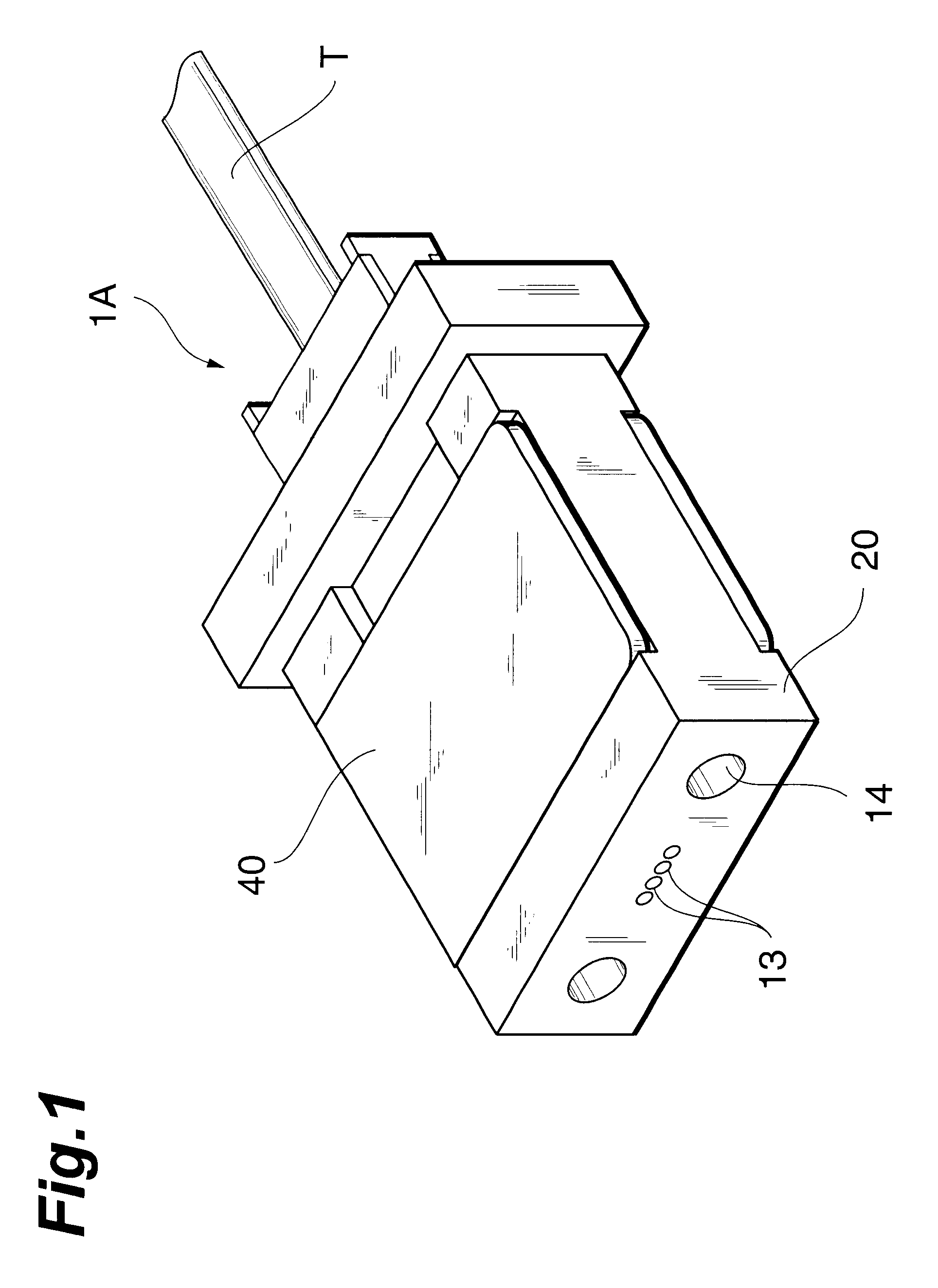
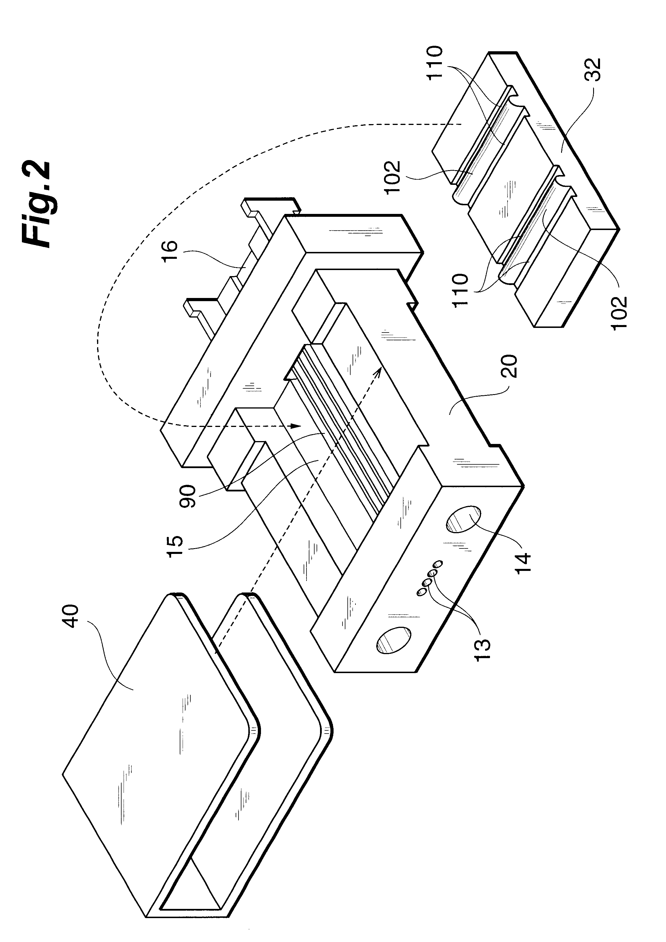
FIGS. 1 and 2 show an optical fiber holder 1A of the present invention. As shown in FIGS. 1 and 2, the holder 1A of this embodiment is comprised of a base member 20 or a so-called ferrule, a lid member 32 received in the base member 20, and a clamper 40 for sandwiching the base member 20 and lid member 32. The holder 1A of this embodiment is abutted against another holder 1A (not shown), so that optical fibers in the two holders are optically connected to each other. For this purpose, the end portions of optical fiber receiving holes 13 for accommodating the distal end portions of the optical fibers, and the end portions of pin insertion holes 14 in which guide pins for positioning the holder 1A are to be inserted, are formed in the distal end face of the base member 20.

The base member 20 is made of a synthetic resin, e.g., a glass-filament-reinforced epoxy-based resin or LCP (Liquid Crystal Polymer), and has an receiving cavity 15 at its center to accommodate the lid member 32. Fo...

second embodiment

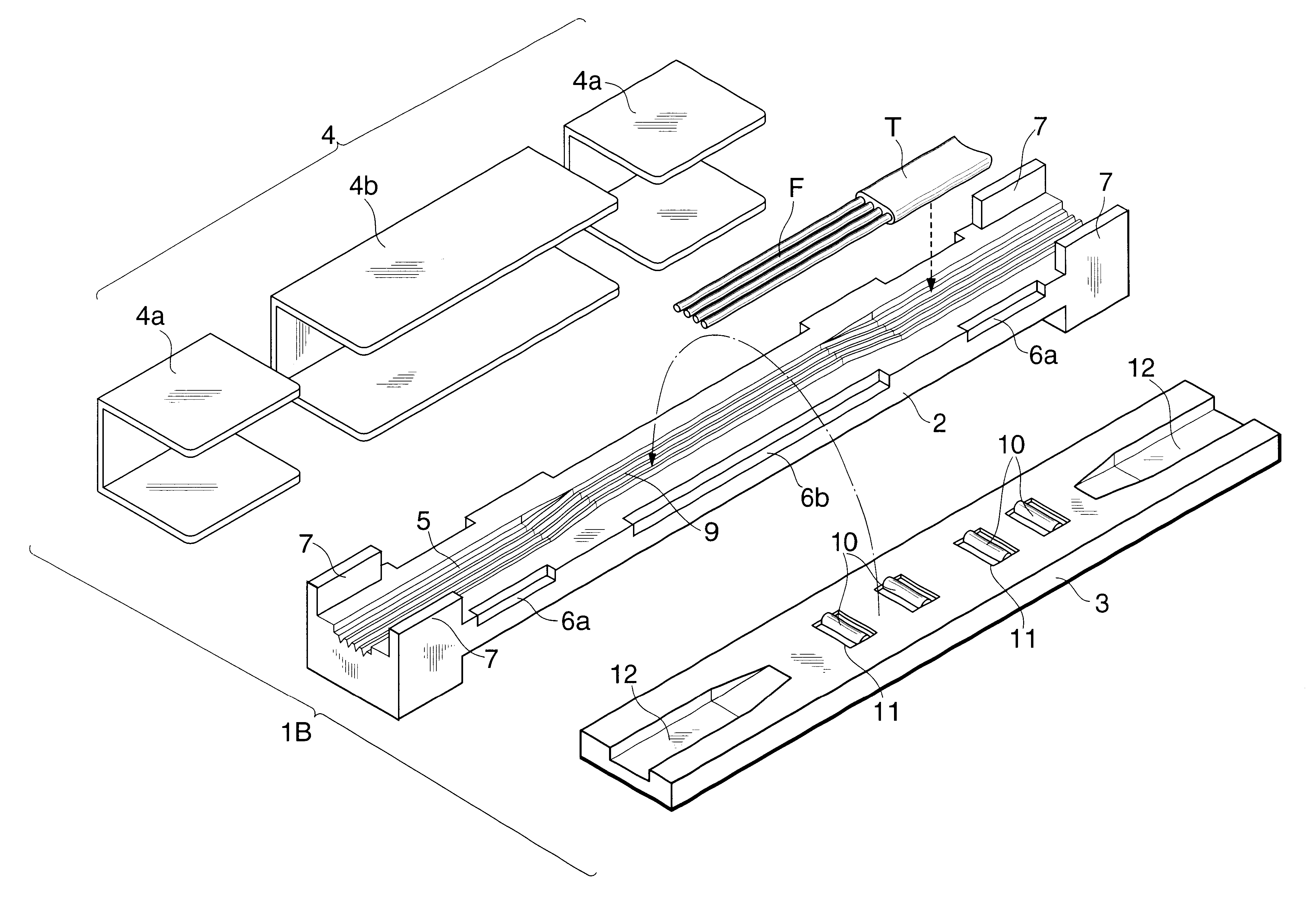
The embodiment described above is a mechanical clamping type optical connector which holds a plurality of optical fibers F by aligning them parallel to each other. However, as shown in FIGS. 3 and 4, this embodiment can also be applied to a mechanical splicing optical connector which holds optical fibers F face to face. the present invention shown in FIGS. 3 and 4 will be described.

A holder 1B according to this embodiment is a multi-fiber mechanical splicing optical connector, and is comprised of a base member 2, lid member 3, and clamper 4, as shown in FIGS. 3 and 4.

The base member 2 is made of a synthetic resin, e.g., a glass-filament-reinforced epoxy-based resin, and has four parallel positioning grooves 9 at the central portion of its surface for positioning and aligning optical fibers F. Guide grooves 5 which continue to the positioning grooves 9 are formed at the two end portions of the base member 2, so that the optical fibers F can be easily guided to the positioning grooves...


PUM


Abstract

An optical fiber holder 1B is an optical fiber holder for holding a plurality of optical fibers in line, and includes a base member 20 with a plurality of parallel positioning grooves 90 for positioning and aligning the plurality of optical fibers, and a lid member 32 adapted to cover the plurality of positioning grooves 90 and to fix the plurality of optical fibers, arranged in the positioning grooves 90, by pressing against the bottom portions of the positioning grooves 90. The lid member 32 has small projections 102 on its portion which comes into contact with the optical fibers.

Description

The present invention relates to an optical fiber holder such as a mechanical splicing or clamping type optical connector for holding optical fibers by vertically sandwiching them.Conventionally, an optical fiber holder for holding optical fibers by vertically sandwiching them such as a mechanical splicing or clamping type optical connector, is known. As an example of such a mechanical splicing optical connector, one described in Japanese Patent Laid-Open No. 9-318836 is known.Although optical fibers held by such an optical fiber holder are manufactured to have a predetermined diameter, they inevitably have small diameter errors due to manufacturing errors. For example, a generally widely used optical fiber with a nominal diameter of 125 .mu.m usually has a diameter error of approximately 1 .mu.m to several micrometers.DISCLOSURE OF INVENTIONSince the diameters of optical fibers have small errors in this manner, when a plurality of optical fibers are to be held by vertically sandwic...

Claims


Application Information

Patent Timeline
Patent Type & Authority Patents(United States)
IPC IPC(8): G02B6/38G02B6/36G02B6/24
CPCG02B6/3636G02B6/3839G02B6/3855G02B6/3858G02B6/3806G02B6/3652G02B6/3696G02B6/3885
Inventor UEDA, TOMOHIKOOHTSUKA, KENICHIROKAKII, TOSHIAKI
Owner SUMITOMO ELECTRIC IND LTD
Why Eureka
Try Eureka