Fluid dispensing closure

a technology of dispensing closure and fluid, which is applied in the direction of liquid transfer devices, transportation and packaging, pliable tubular containers, etc., can solve the problems of uninterrupted fluid flow from the container, container users, etc., and achieve the effect of effectively venting the dispensing closure and being less expensiv

Inactive Publication Date: 2002-04-30
RIEKE LLC
View PDF36 Cites 69 Cited by
  • Summary
  • Abstract
  • Description
  • Claims
  • Application Information

AI Technical Summary

Benefits of technology

The fluid dispensing closure of the present invention includes a substantially cylindrical housing adapted to be threadably attached to the container. A cylindrical dispensing spout, in fluid communication with the container, extends from the housing. A valving member is disposed within the dispenser spout to control fluid flow therethrough. In a preferred embodiment the valving member comprises a resilient elastomeric valve element that is seated within the dispenser spout to control fluid flow. This one-piece valve element replaces the more standard valve mechanisms that usually comprise multiple components, for example, a ball and spring configuration, or a plunger and washer assembly. Hence, the instant invention is less expensive and simpler to manufacture.
The dispenser spout accommodates a venting assembly, which includes a vent passageway in communication with a vent opening. A vent grommet is captured within the vent passageway for selectively closing the vent opening in response to the accumulated vacuum pressure created as the liquid is dispensed from the container. This action effectively vents the dispensing closure.

Problems solved by technology

Further, it is important that the fluid flow from the container is uninterrupted.
Although this is a workable solution, it presents problems for the container manufacturers in that two separate openings must be made in the container.
It also creates problems for the container users because the second opening, typically a simple vent hole, is difficult to seal while the container is being filled, stored and transported.

Method used


Image

  • Fluid dispensing closure
  • Fluid dispensing closure
  • Fluid dispensing closure

Examples


Embodiment Construction

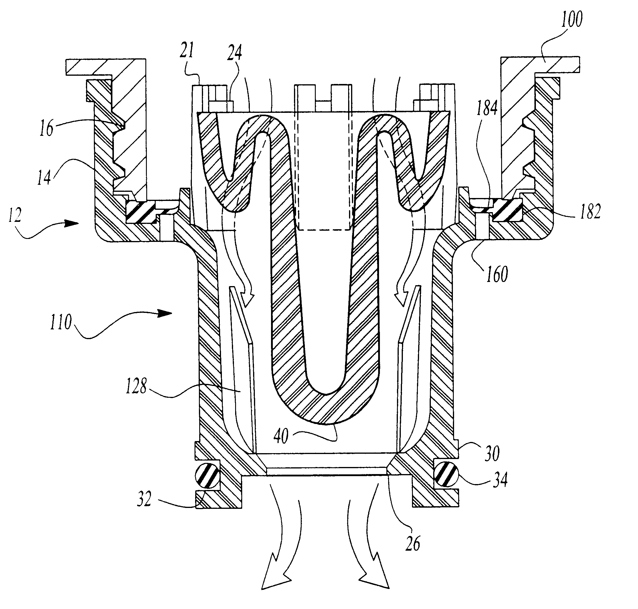
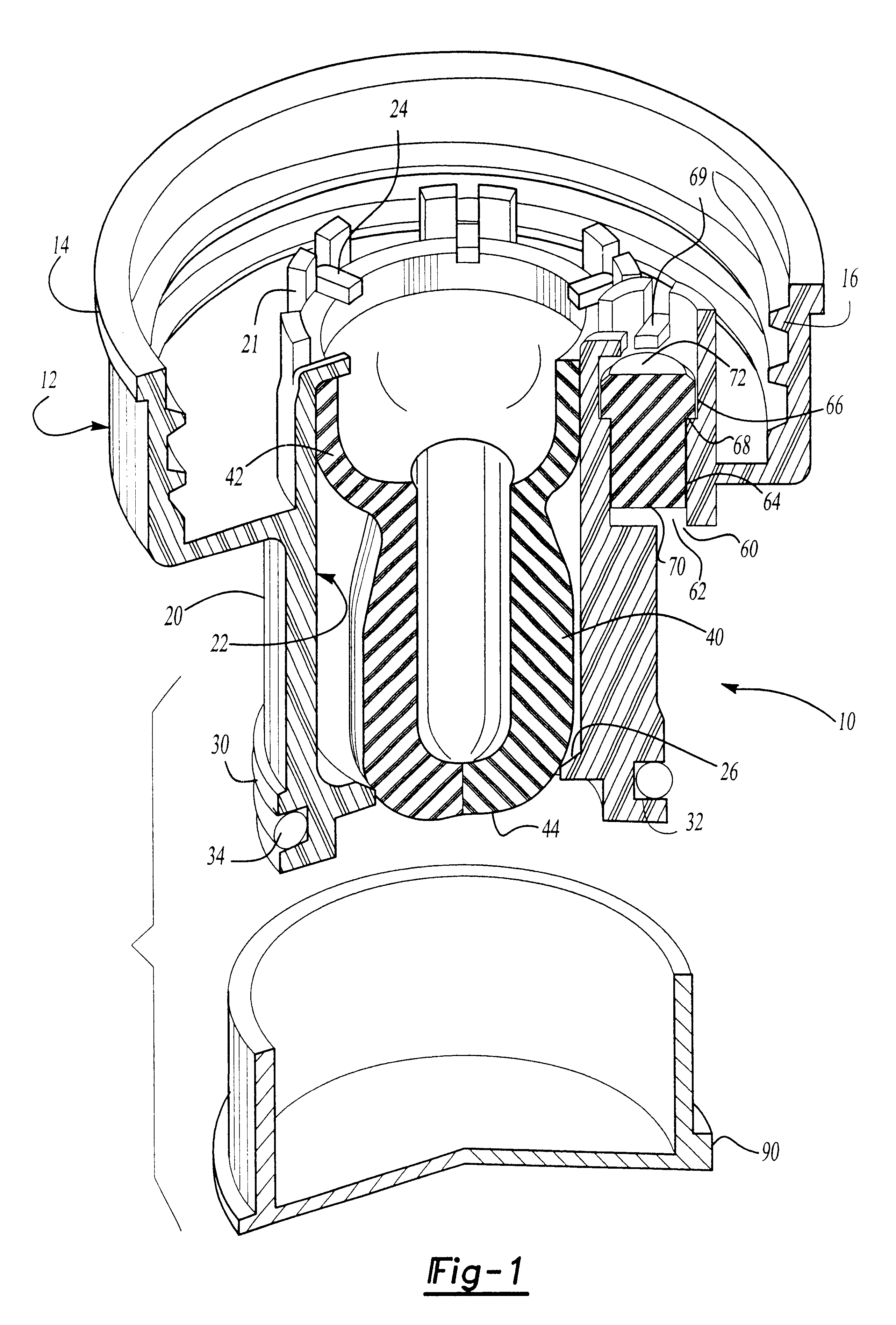
FIG. 1 illustrates a preferred embodiment of the invention in which a fluid dispensing closure 10 is shown. The closure 10 attaches at one end to a bulk fluid container 100 or, for example, milk or juice, and at the other end to a dispensing system. The closure 10 prevents fluid from leaking during the transportation and storage of the bulk container 100. Further, the closure 10 permits the selective dispensing of fluid from the container 100 to the dispensing system without an interruption in the fluid flow from the container 100.

Referring to FIG. 1, the closure 10 comprises a housing 12, a resilient valve assembly 40, and an overcap 90. The housing 12 is adapted to be secured to the bulk container 100. The housing 12 has an upper attachment portion 14 and a downward-extending dispensing spout 20. In a preferred embodiment, the upper attachment portion 12 incorporates mating threads 16 for the threaded engagement with the bulk container 100.

The downward-extending dispensing spout 2...


PUM


Abstract

A fluid dispensing closure which incorporates a dispensing valve to control fluid flow through the closure and a vent passageway to vent air into the container as necessary. The closure includes a dispensing spout capable of mating engagement with a receiving container. The dispenser spout has a fluid passageway with a resilient valve made from an elastomeric material seated therein. The vent passageway formed in the closure is selectively sealed by a grommet depending upon the vacuum created within the container as the fluid is being dispensed from the container. A removable overcap sealingly covers the dispensing spout to capture any fluid leakage.

Description

I. Field of the InventionThis invention relates to a fluid dispensing closure for selectively dispensing fluids such as juices into a desired container and, in particular, to a dispenser matingly engageable with a receiving container and including, in combination, a resilient spring-biased dispensing valve and a vent valve.II. Description of the Prior ArtA variety of closures have been developed for selective control of fluid flow from a container. The most common closure incorporates a valve which may be rotated or otherwise manually opened and closed to dispense fluid from the container. The dispensing closure is typically situated near the bottom of the container allowing gravity to force fluid through the closure.Commercial beverage dispensers incorporate mechanical dispensing means associated with the housing. Examples include commercial milk and juice dispensers that have external dispensing systems. Here, the juice or milk is transported in bulk containers. The mechanical dis...

Claims


Application Information

Patent Timeline
Patent Type & Authority Patents(United States)
IPC IPC(8): B67D1/00B67D3/00B67D5/02B67D3/02B67D1/08B67D5/01B65D47/26B65D51/16B67D7/02
CPCB67D1/0835B67D7/0294B67D3/02
Inventor ROHR, ROBERTKASTING, THOMASBEAVER, JEFFREY L.
Owner RIEKE LLC
Why Eureka
Try Eureka