
Aircraft door structure

a technology for aircraft and doors, applied in the direction of aircraft floors, fuselages, transportation and packaging, etc., can solve the problems of reducing the pressure sealing characteristics of doors, requiring complicated latching and unlatching mechanisms, etc., to improve the safety of stops, reduce production costs, and reduce the weight of door structures

Inactive Publication Date: 2002-04-30
EUROCOPTER DEUT GMBH
View PDF4 Cites 20 Cited by
  • Summary
  • Abstract
  • Description
  • Claims
  • Application Information

AI Technical Summary

Benefits of technology

to avoid door stop failures in an aircraft door by improving the safety of the stops that support a closed door relative to the aircraft fuselage or body;
to reduce the weight of the door structure by providing redundant door stop features so that standard load conditions can be taken into account for determining door strength rather than maximum load conditions;
to reduce the need for conventionally required door stiffening features by providing redundant door stop features which have a door stiffening effect; and
to reduce production costs by providing door strength where needed and avoiding unnecessary reinforcements.
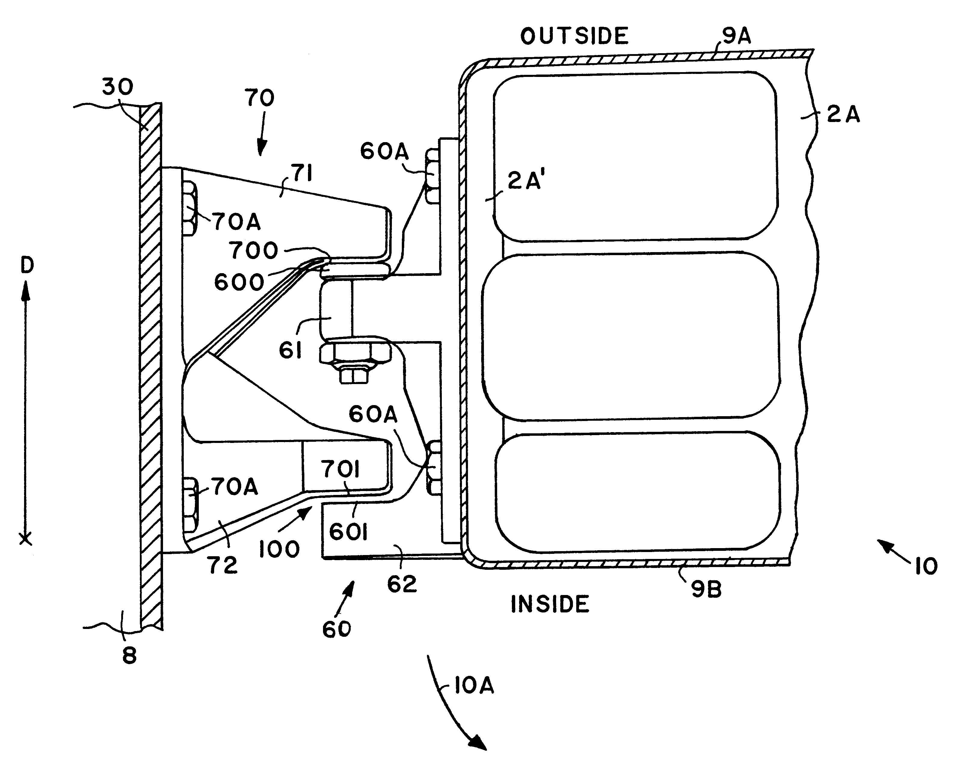
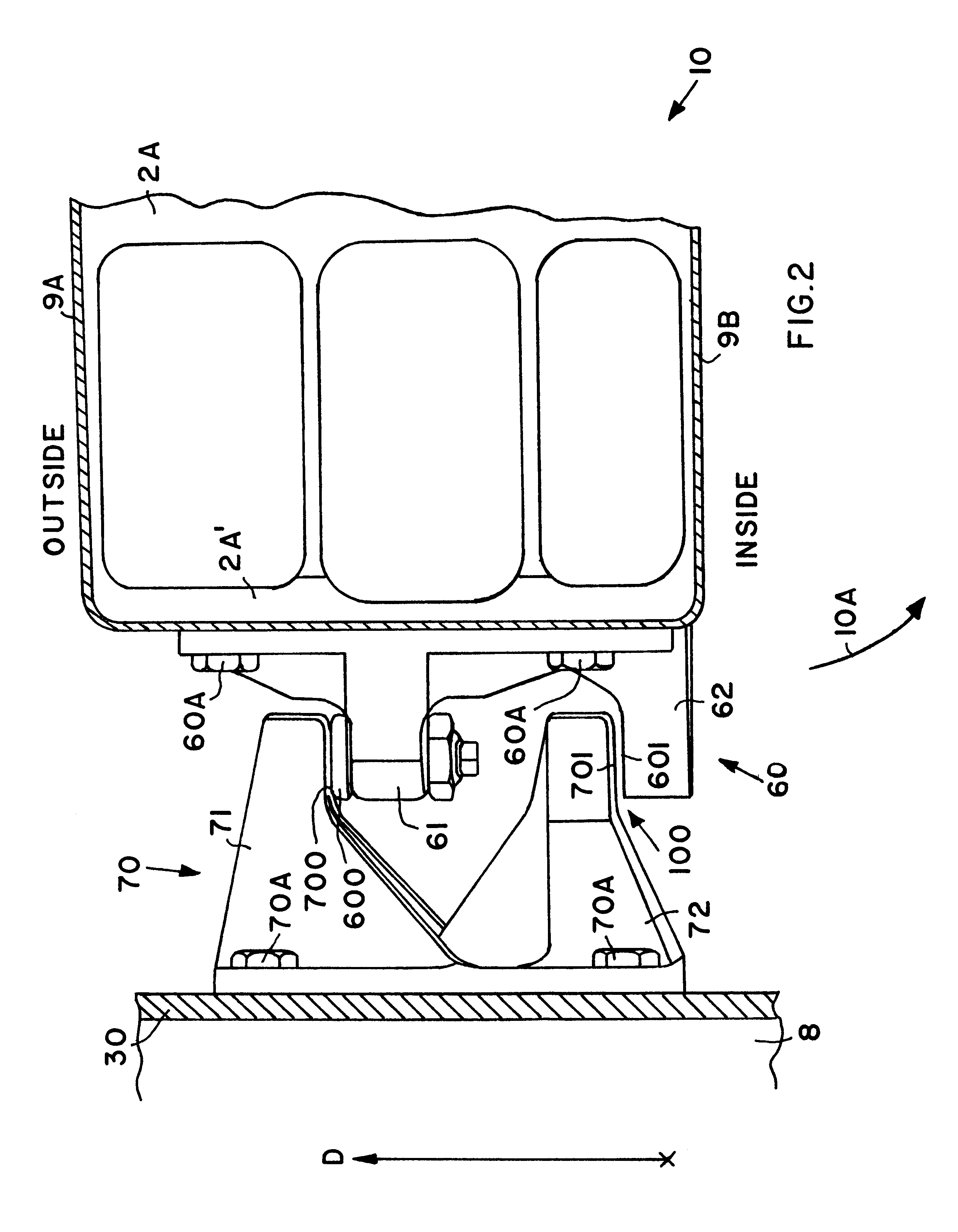
The invention makes it possible to increase safety with little effort and expense. Based on the invention, only the standard load conditions must be taken into account when calculating the strength and dimensions of the door. The heretofore additionally necessary door stiffeners no longer need to be part of the construction criteria for the door structure, whereby a significant weight reduction is achieved even if the stop brackets are heavier because the remaining door structure is lighter than heretofore, which also saves costs.

Problems solved by technology

A complicated latching and unlatching mechanism is required to operate the door.
Such added loads can deform the door structure giving rise to the danger that the door's pressure-sealing characteristics are diminished.

Method used


Image

  • Aircraft door structure
  • Aircraft door structure
  • Aircraft door structure

Examples


Embodiment Construction

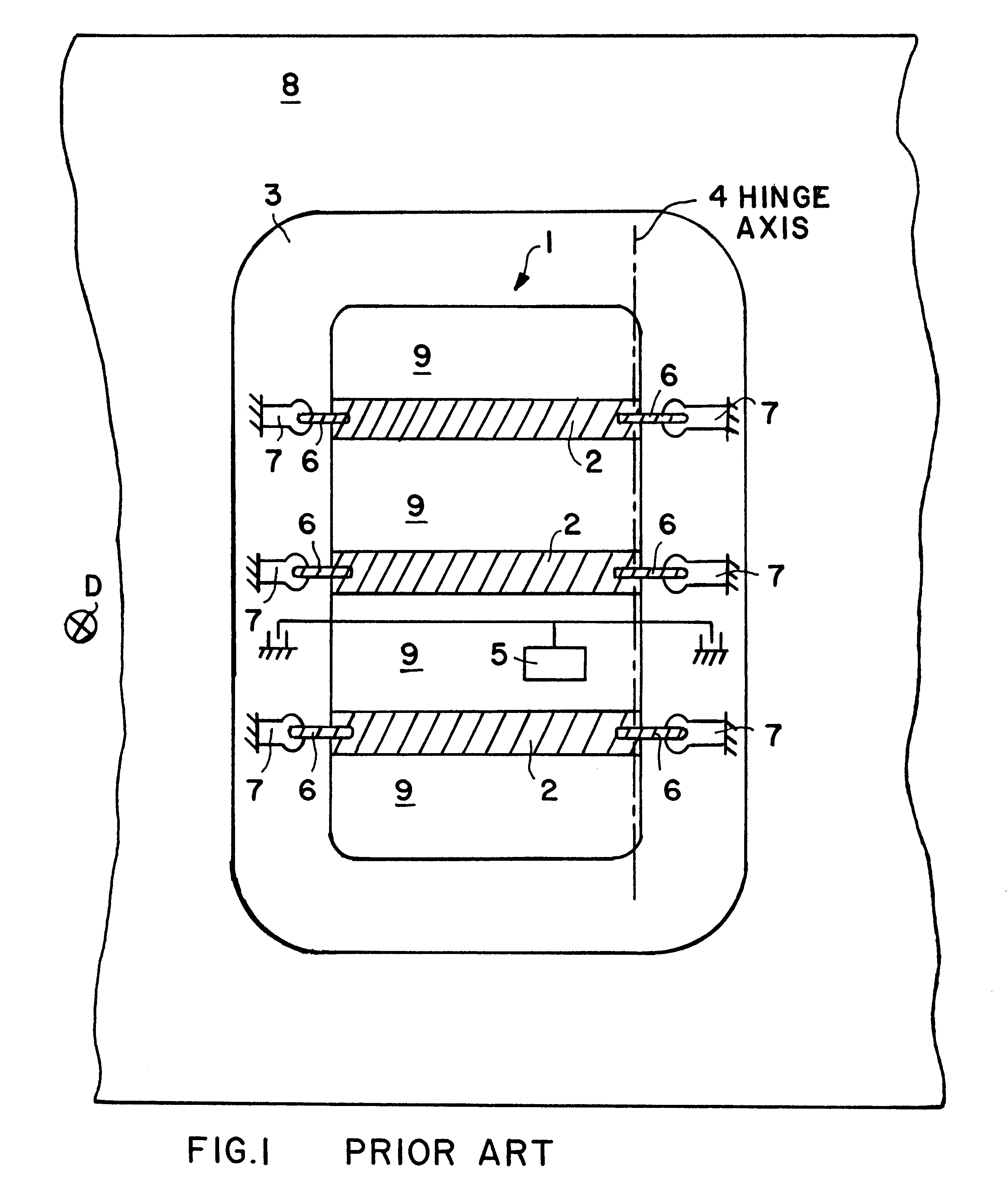
FIG. 1 shows a conventional aircraft door 1 installed in a door opening surrounded by a frame 3 in an aircraft body wall 8. The door 1 comprises a plurality of load bearing beams 2 positioned in several different, usually horizontal, planes and spaced apart from each other. The beams may be arranged in any plane including horizontal planes. The invention does not depend on the orientation of the beams 2. As shown the door 1 is closed and seen from the interior of the fuselage. Such a door can be used in fixed-wing aircraft, rotary-wing aircraft or in transport capsules of a balloon and in any pressurized container.

The length of the shown load bearing beams 2 is the same as the width of the door 1. The beams 2 are connected to the skin or cladding 9 of the door. Each individual beam 2 comprises at each beam end a single stop member 6 with a bearing surface facing outwardly in the load direction D shown as a cross in a circle. When the door 1 is in its shown closed position, the beari...


PUM


Abstract

A door for an enclosed space under pressure, such as an aircraft cabin, has redundant door stops secured to the door edges and cooperating with redundant frame stops secured to a door frame in an aircraft body. The door stops and the frame stops are arranged in pairs. A first pair of stops is effective under normal operating conditions to keep the door in a sealed position in the door frame. A second pair which is not transmitting any loads under normal operating conditions, becomes effective immediately when one and / or both stop components of the first pair fails. For this purpose the stop member and stop element forming the second pair are normally spaced from each other by a gap that is small enough to close instantly in response to failure of the first pair of stops.

Description

PRIORITY CLAIMThis application is based on and claims the priority under 35 U.S.C. .sctn.119 of German Patent Application 199 23 441.8, filed on May 21, 1999, the entire disclosure of which is incorporated herein by reference.The invention relates to an aircraft door structure with a door and a frame. The door has at least several load bearing beams spaced apart from each other and sandwiched between inner and outer door skins or claddings. Each beam end carries a stop member. When the door is closed the stop member bears against a stop element secured to the door frame surrounding a door opening in the aircraft body.BACKGROUND INFORMATIONThe pressure difference which arises in flight, between the passenger cabin and the outer atmosphere, results in pressure loads which need to be taken up by the door structure and transferred to the door frame which transmits these forces to the aircraft's fuselage structure. The pressure loads applied at the door act in the direction of the pressu...

Claims


Application Information

Patent Timeline
IPC IPC(8): B64C1/00B64C1/14E06B7/22
CPCB64C1/1423B64C1/1407
Inventor ERBEN, HANNES
Owner EUROCOPTER DEUT GMBH
Learn More