Reclosing apparatus for auxiliary systems

a technology for auxiliary systems and closing apparatuses, which is applied in the direction of electrical equipment, emergency protective circuit arrangements, circuit arrangements, etc., can solve the problems of excessive conservative protection response, high-voltage busbar voltage drop, and disconnection of auxiliary systems

Inactive Publication Date: 2002-05-07
ABB (SCHWEIZ) AG
View PDF7 Cites 5 Cited by
  • Summary
  • Abstract
  • Description
  • Claims
  • Application Information

AI Technical Summary

Problems solved by technology

Such a transient fault causes, for example, a sudden voltage drop on the high-voltage busbar.
This voltage drop is transformed to the medium-voltage and low-voltage levels, and can lead to disconnection of the auxiliary systems.
The unavoidable inaccuracies in the simulation of disturbance sit

Method used


Image

  • Reclosing apparatus for auxiliary systems
  • Reclosing apparatus for auxiliary systems
  • Reclosing apparatus for auxiliary systems

Examples


Embodiment Construction

The object of the invention is therefore to provide a reclosing apparatus of the type mentioned initially, which overcomes the disadvantages mentioned above.

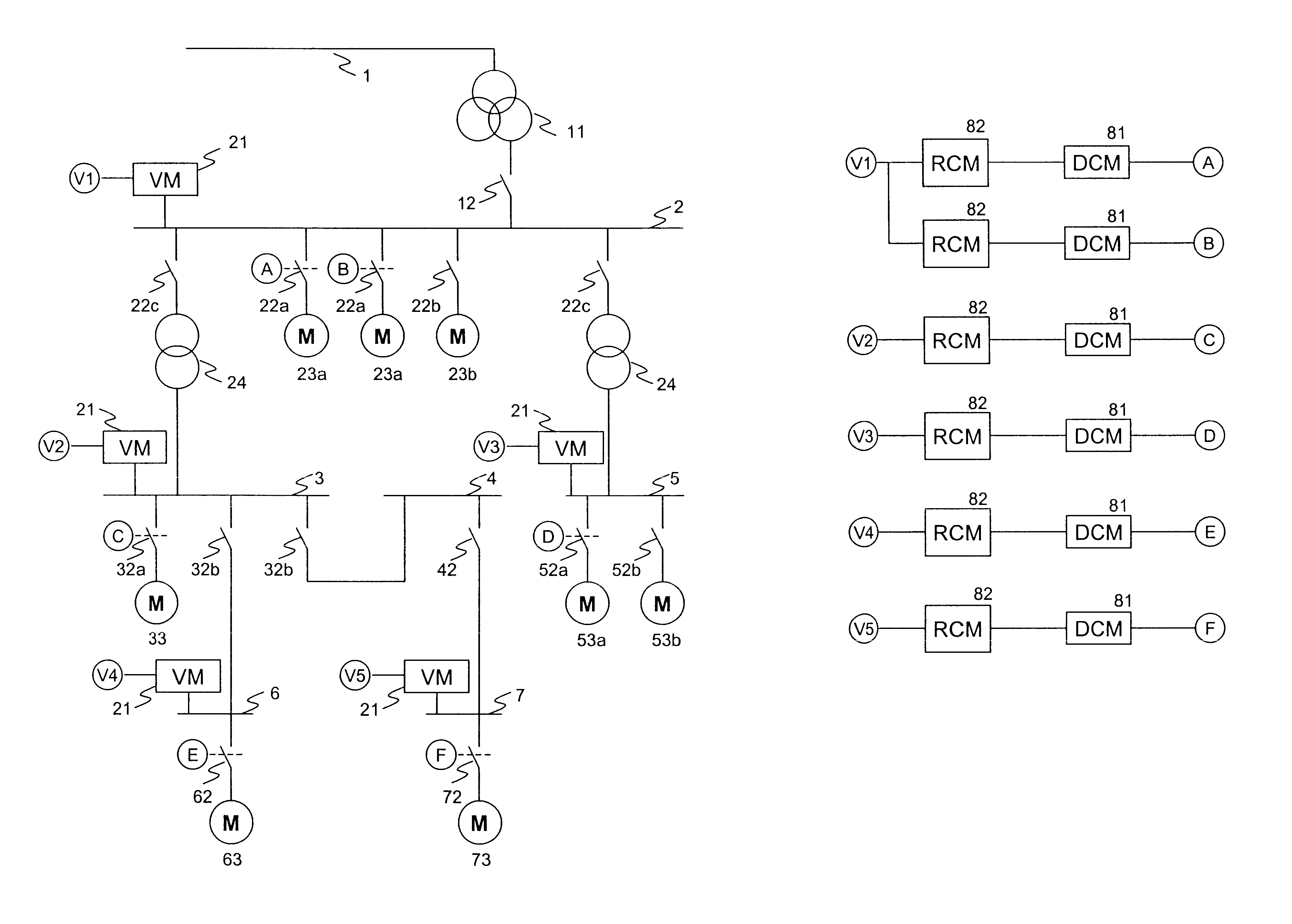
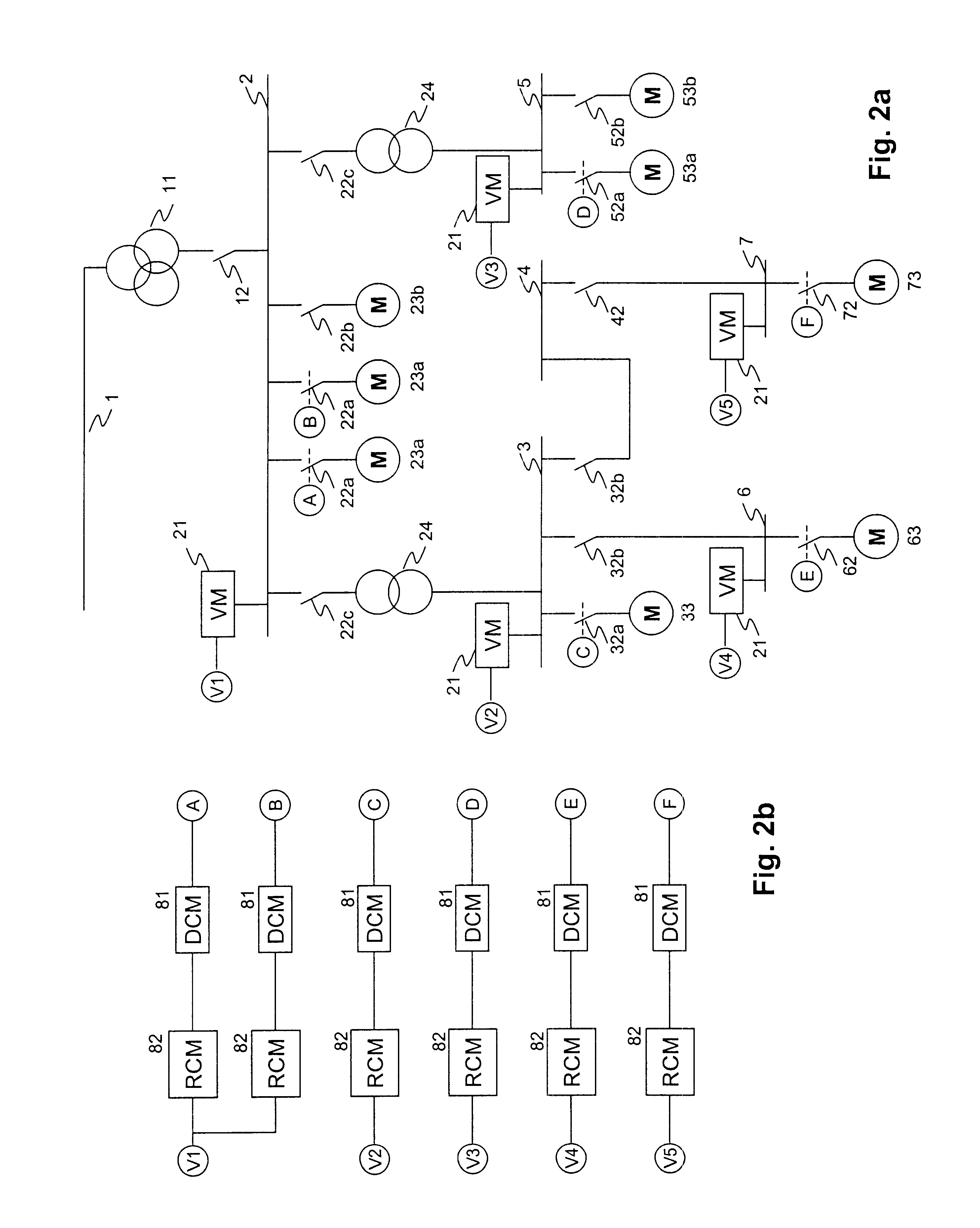
In the reclosing apparatus according to the invention, a dedicated reclosing module is assigned to a drive module for each drive for which reclosing is desired.

In consequence, it is possible to set the reclosing time individually for each drive. There is no coupling module between different reclosing modules, leading to considerable simplification of the design complexity and eliminating fault sources.

The reclosing module is designed as a functional module which is separate from a drive module, so that drives in which there is no need for reconnection can be operated with the same drive modules.

In one preferred embodiment of the subject matter of the invention, drive groups are defined in order to limit overloading of the auxiliaries transformers as well as voltage transients during reclosing. A drive group is defined by setting...


PUM


Abstract

A reclosing apparatus for the auxiliary systems of a plant, in particular a power station, has drive modules (81) for actuating electrical drives (23a, 23b, 33, 53a, 53b, 63, 73) of the auxiliary systems. Each drive module (81) of a reclosable drive (23a, 33, 53a, 63, 73) is assigned a reclosing module (82). When a voltage interruption occurs, the reclosing modules (82) switch the drives (23a, 33, 53a, 63, 73) by opening switches (22a, 32a, 52a, 62, 72). If the end of the voltage interruption is detected within a predetermined time, the reclosing modules (82) switch the drives (23a, 33, 53a, 63, 73) on again. Each busbar (2, 3, 5, 6, 7) which supplies a drive (23a, 33, 53a, 63, 73) provided with a reclosing module (82) is equipped with a microprocessor-controlled voltage monitoring device (21).

Description

The invention relates to the field of electrical and control systems, in particular power station control systems.PRIOR ARTSuch a reclosing apparatus is known, for example, from the product documentation "BBC Reclosing Device", D KWL 6309 94 E 04 / 95.FIG. 1a shows an example of an arrangement in which a reclosing apparatus according to the prior art is used. The figure shows an electrical network for supplying auxiliary systems in a power station plant, for example a gas turbine or combined power station. Such auxiliary systems are preferably used for supplying cooling water, fuel, lubricating oil, hydraulic oil or cooling air. A high-voltage busbar which is connected to a high-voltage network uses an auxiliaries transformer 11 to supply a plurality of busbars 2, 3, 4, 5, 6, 7, and uses medium-voltage transformers 24 to supply a plurality of medium-voltage and low-voltage drives (23a, 23b, 33, 53a, 53b, 63, 73 for the auxiliary systems. A single voltage monitoring device 21 is connec...

Claims


Application Information

Patent Timeline
IPC IPC(8): H02J11/00
CPCH02J11/00
Inventor PEDNEKAR, SUDHIRSCHLETT, HANS-WERNERBLATTER, RICHARDGOEBELBECKER, THEO
Owner ABB (SCHWEIZ) AG
Why Eureka
Try Eureka