
Rotation restricted barrel lock and key

Inactive Publication Date: 2002-05-14
DEWALCH TECH INC
View PDF20 Cites 41 Cited by
  • Summary
  • Abstract
  • Description
  • Claims
  • Application Information

AI Technical Summary

Benefits of technology

The present invention provides a means for inducing the relative rotation of a barrel lock and key when the key is turned. This means comprises a sleeve rotatably mounted on the key. This sleeve non-rotatably couples the lock via complementary prongs and notches on the sleeve and the lock, respectively. The user can easily prevent the lock from rotating by holding the sleeve stationary when the key is turned. Because the notches are on the top of the lock, the present invention can be used even when the lock is encased on all sides by the locking hardware. Furthermore, the present invention does not prevent axial movement of the lock, and therefore allows removal of the lock from the locking hardware.

Problems solved by technology

The set screw of the prior art prevents any axial movement of the lock, and thus hinders easy removal of the lock.

Method used


Image

  • Rotation restricted barrel lock and key
  • Rotation restricted barrel lock and key
  • Rotation restricted barrel lock and key

Examples


Embodiment Construction

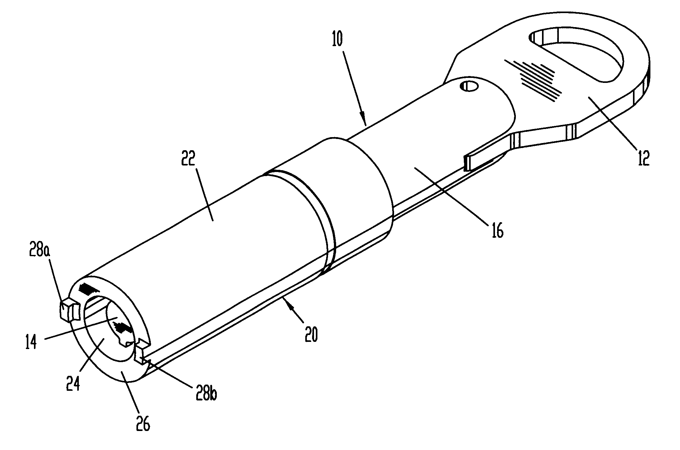
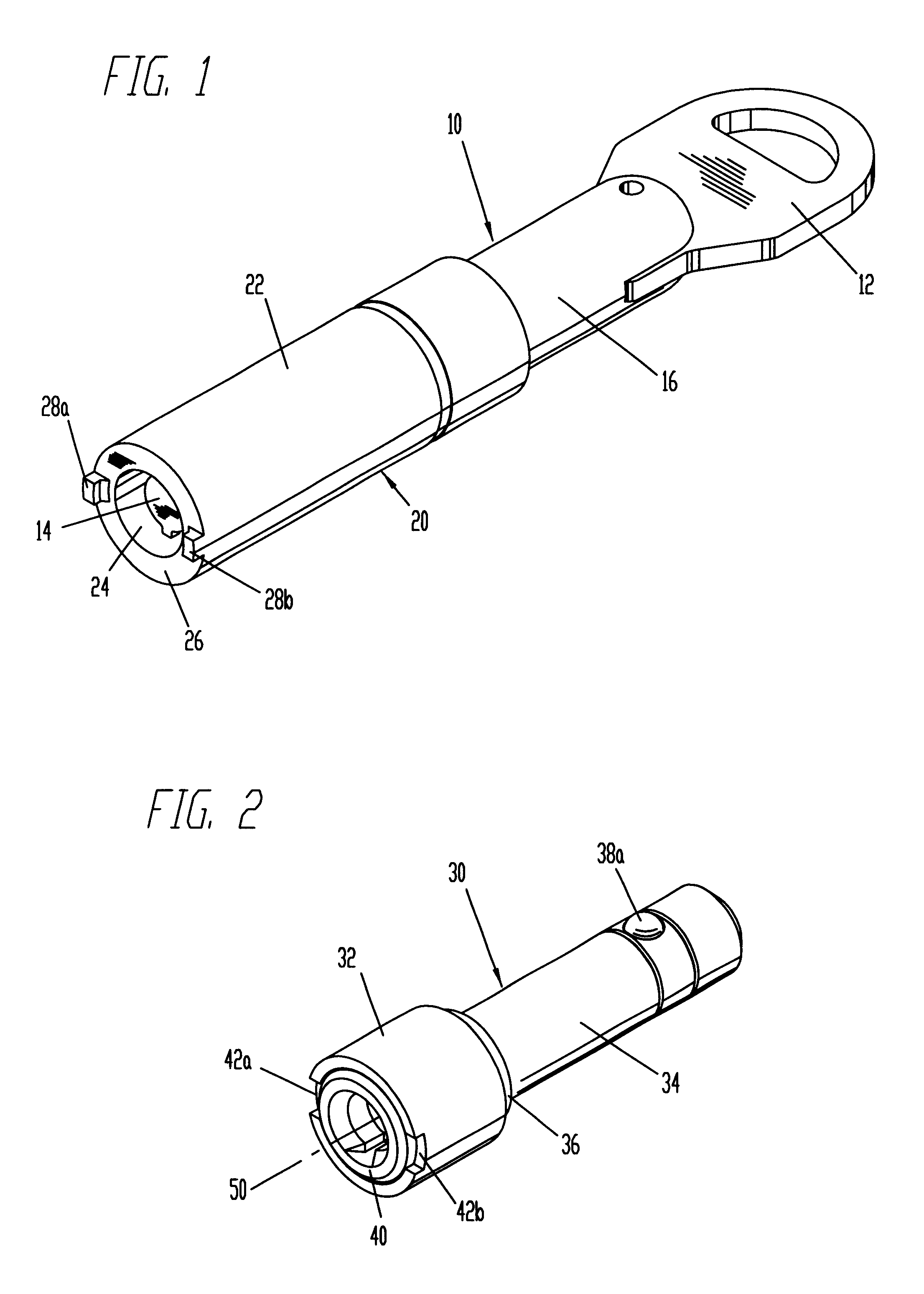
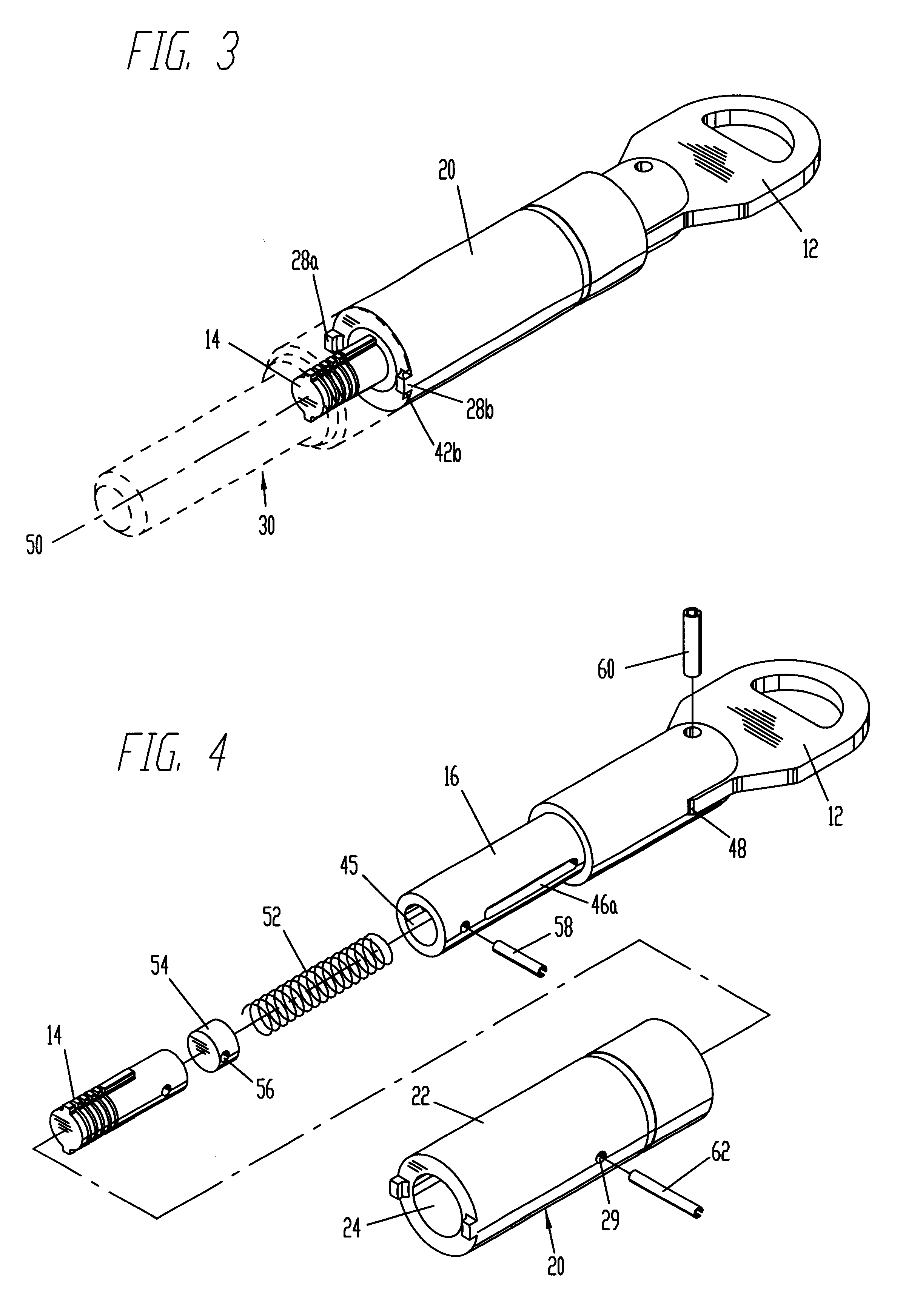
Referring to FIG. 1, the preferred embodiment key 10 comprises a handle 12 at one end, heretofore referred to as the top end; and a lock actuating portion or bit assembly 14 at the bottom end. The handle and bit assembly are each rigidly attached to the shaft 16. The lock coupling member or sleeve 20 is slidably and rotatably attached to the shaft 16, and comprises an outer wall 22, a central cavity 24, and an interlocking surface 26 with prongs 28a and 28b. Referring to FIG. 2, the preferred embodiment barrel lock 30 comprises a head portion 32, a smaller diameter shank portion 34, and a shoulder portion 36 between the head and shank portions. Extensible steel balls such as 38a serve to retain the barrel lock 30 in its locking hardware. At the end of the head portion 32 is the key receiving face 40, which includes notches 42a and 42b.

As shown in FIG. 3, when the key 10 is used to actuate the barrel lock 30, the sleeve 20 slides towards the top end of the key, exposing the bit assem...


PUM


Abstract

A rotation restricted barrel lock and key includes a rotationally actuated barrel lock and a key for opening the lock. The key comprises a lock engaging portion rigidly attached to a handle, and a sleeve rotatably mounted on the handle shaft. The sleeve may slide axially along the shaft within preset limits. Lock actuation is characterized by rotation of the lock engaging portion of the key relative to the lock. During actuation of the lock, a set of prongs on the sleeve engages a complementary set of notches on the barrel lock, thereby non-rotatably coupling the barrel lock to the sleeve. By grasping the sleeve, the user can prevent rotation of the lock while turning the key handle, and thus actuate the lock.

Description

1. Field of the InventionThis invention relates to barrel locks, specifically to means for inducing relative rotation between a barrel lock and a key.2. Problems Addressed by the InventionBarrel locks are used to secure meter rings like the one shown in U.S. Pat. No. 4,702,093 (DeWalch, 1987), as well as a variety of other locking hardware. In the present disclosure, the term "locking hardware" is used to refer to any device which is secured by a barrel lock. A barrel lock, as defined in the present disclosure, is commonly characterized as having a generally cylindrical case with a head portion, a smaller diameter shank portion, and a shoulder portion interposed between the head and shank portions. The shank portion includes retaining means, usually a pair of retractable steel balls, to prevent extraction of the lock from the meter ring or other locking hardware when the lock is locked. Usually barrel locks are removed from the locking hardware when they are unlocked. In many cases ...

Claims


Application Information

Patent Timeline
IPC IPC(8): E05B19/00E05B67/00E05B67/36E05B15/02E05B63/00E05B15/00E05B19/02
CPCE05B67/365E05B19/00E05B15/0205E05B15/022E05B63/003Y10T70/443Y10T70/7802Y10T70/7814Y10T70/7819Y10T70/7853Y10T70/8622
Inventor DEWALCH, NORMAN BINZ
Owner DEWALCH TECH INC
Features
  • Generate Ideas
  • Intellectual Property
  • Life Sciences
  • Materials
  • Tech Scout
  • Unparalleled Data Quality
  • Higher Quality Content
  • 60% Fewer Hallucinations
Learn More