Cooling apparatus for liquid-cooled internal combustion engine

a liquid-cooled internal combustion engine and cooling apparatus technology, which is applied in the direction of engine cooling apparatus, machines/engines, measurement devices, etc., can solve the problems of affecting the control accuracy of the inlet temperature, affecting the flow rate detector, sensor and the line, and difficult to accurately control the cooling water temperature at the cooling water inlet side of the engin

Inactive Publication Date: 2002-05-21
DENSO CORP
View PDF4 Cites 54 Cited by
  • Summary
  • Abstract
  • Description
  • Claims
  • Application Information

AI Technical Summary

Benefits of technology

Accordingly, the cooling water temperature at the inlet of the engine is accurately controlled since the flow control valve is controlled by parameters including the flow rate without detecting the flow rate of the cooling water.

Problems solved by technology

However, it was difficult to accurately control the cooling water temperature at the cooling water inlet side of the engine (hereinafter referred to as "the inlet temperature") because of the following reason.
Accordingly, the change of the flow rate caused by the change of the valve opening amount is not reflected to the control of the flow control valve, and the control accuracy of the inlet temperature is compromised.
However, it is practically difficult to place a flow rate detector, sensor and the line in the engine room because of the mounting space and the cost thereof.

Method used


Image

  • Cooling apparatus for liquid-cooled internal combustion engine
  • Cooling apparatus for liquid-cooled internal combustion engine
  • Cooling apparatus for liquid-cooled internal combustion engine

Examples


Embodiment Construction

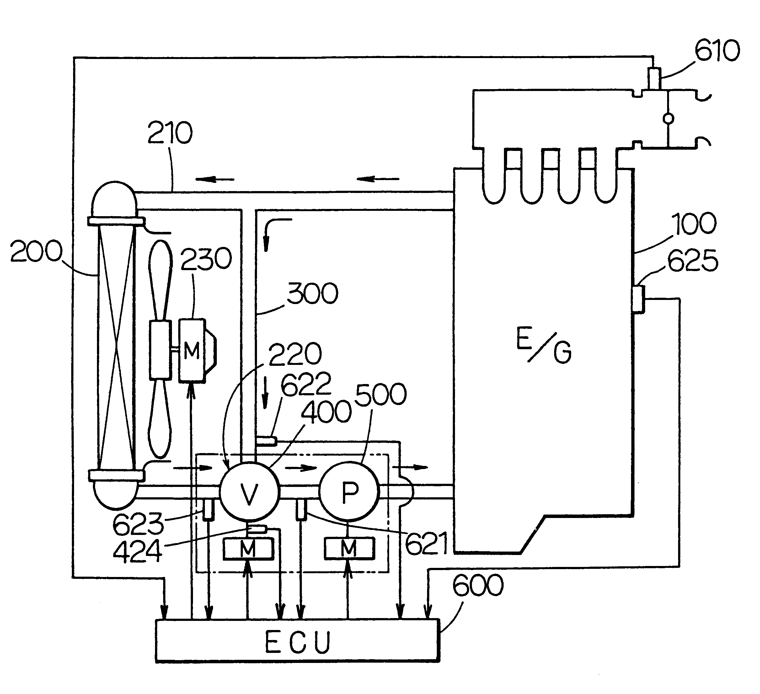
A cooling apparatus for a liquid-cooled internal combustion engine of the present invention applied to a water-cooled engine of a vehicle is shown in FIGS. 1 to 8 as an embodiment of the present invention.

In FIG. 1, a radiator 200 cools cooling water (coolant) which circulates in the water-cooled engine 100. The cooling water circulates through the radiator 200 via a radiator passage 210.

A part of the cooling water flowing out from the engine 100 can be introduced to an outlet side of the radiator 200 at the radiator passage 210 by bypassing the radiator 200 via a bypass passage 300.

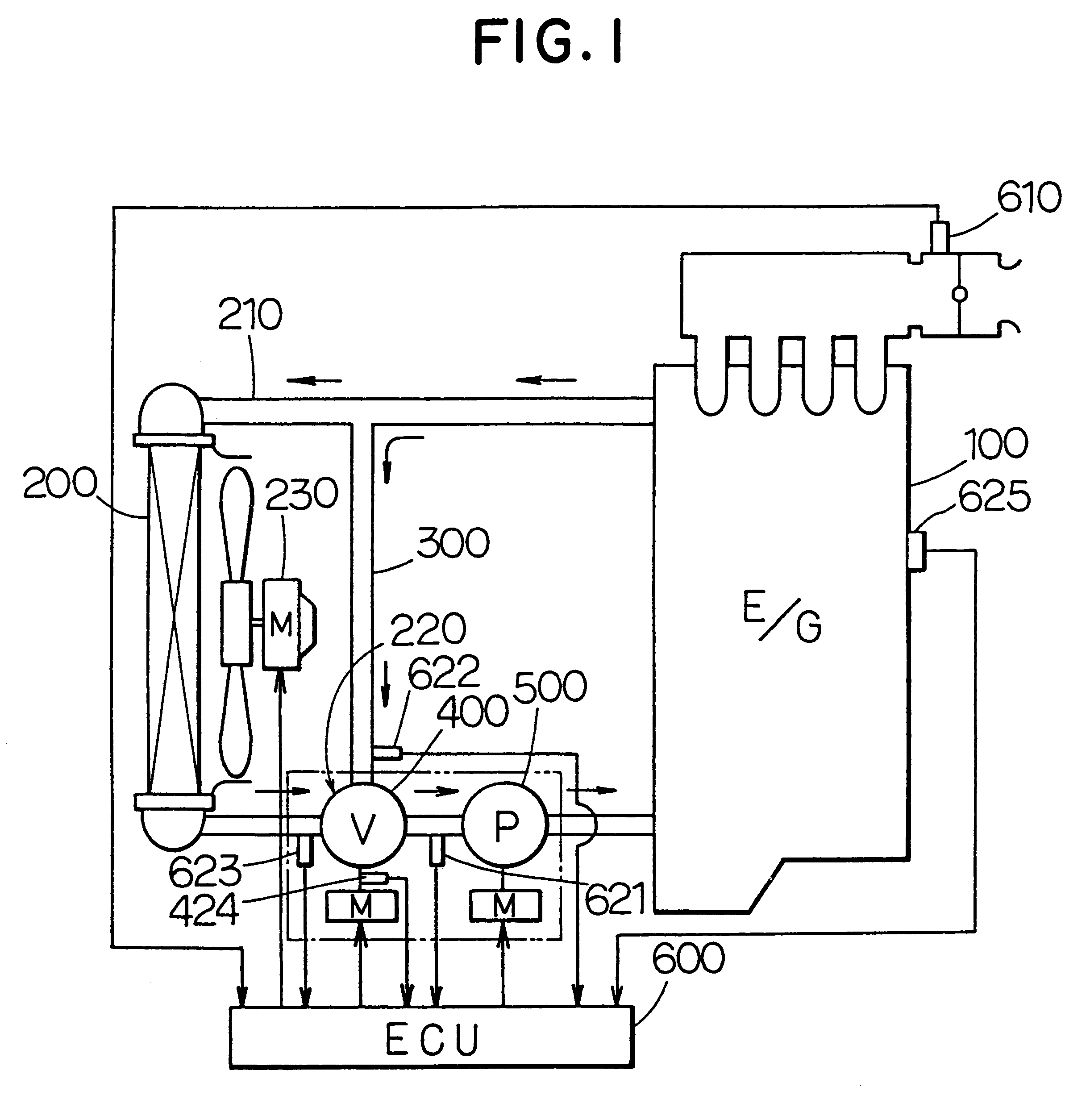
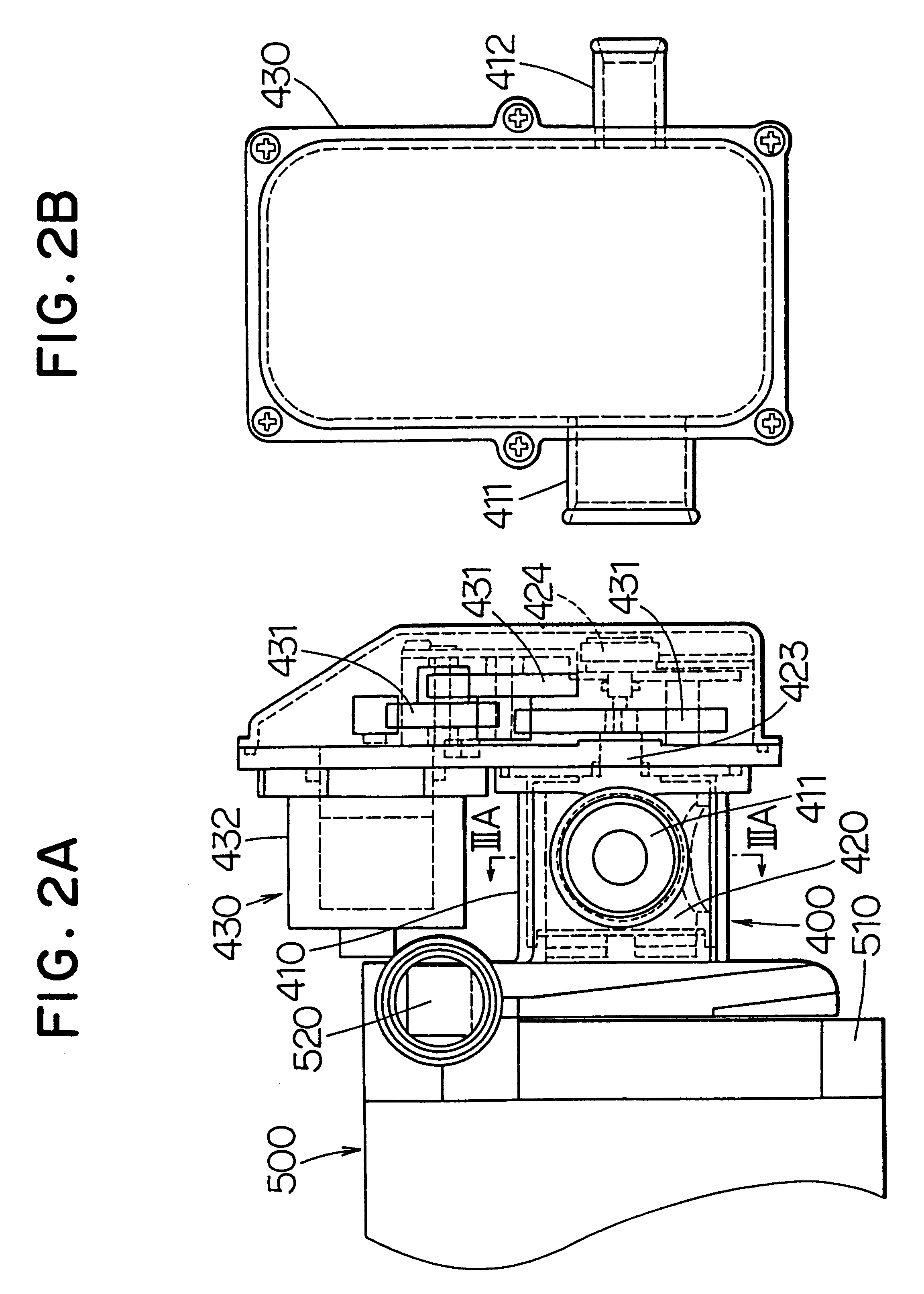
A rotary-type flow control valve 400 is provided at a junction 220 between the bypass passage 300 and the radiator passage 210 to control the flow rate of the cooling water passing through the radiator passage 210 (hereinafter referred to as "the radiator flow rate Vr") and the flow rate of the cooling water passing through the bypass passage 300 (hereinafter referred to as "the bypass flow rate Vb").

An ...


PUM


Abstract

A flow rate ratio of a radiator flow rate to a bypass flow rate is determined from pump water temperature, bypass water temperature and radiator water temperature. The relation between the flow rate ratio and a valve opening degree of a flow control valve is predetermined as a map. The valve opening degree is determined from the flow rate ratio and the map. Accordingly, the cooling water temperature at an inlet of a pump is accurately controlled without detecting the flow rate of the cooling water.

Description

This application relates to Japanese Patent Application No. Hei. 10-214493 filed Jul. 29, 1998, the entire contents of which are incorporated herein by reference.1. Field of the InventionThe present invention relates to a cooling apparatus for a liquid-cooled internal combustion engine, such as a water-cooled engine, and it is preferably applicable to an internal combustion engine of a vehicle.2. Description of Related ArtIt is necessary to keep the engine cooling water temperature appropriate in order to drive the engine efficiently.One type of known cooling apparatus for an engine is disclosed in JP-A-63-268912. The cooling apparatus disclosed in JP-A-63-268912 controls the engine cooling water temperature based on a wall surface temperature of the cylinder block of the engine.In order to appropriately control the engine cooling water temperature at a cooling water inlet of an engine, the inventors of the present invention tried to develop a cooling apparatus having a flow control...

Claims


Application Information

Patent Timeline
Patent Type & Authority Patents(United States)
IPC IPC(8): F01P7/16F01P7/14F01P5/12F01P7/04
CPCF01P7/048F01P7/164F01P7/167F01P2005/125F01P2007/146F01P2025/64F01P2025/30F01P2025/32F01P2025/36F01P2025/50F01P2025/62F01P2025/06
Inventor SUZUKI, KAZUTAKATAKAHASHI, EIZOU
Owner DENSO CORP
Why Eureka
Try Eureka