

Humidification unit, method of making same, and ventilatory system using such a humidification unit
- Summary
- Abstract
- Description
- Claims
- Application Information
AI Technical Summary
Benefits of technology
Problems solved by technology
Method used
Image

Examples
first embodiment
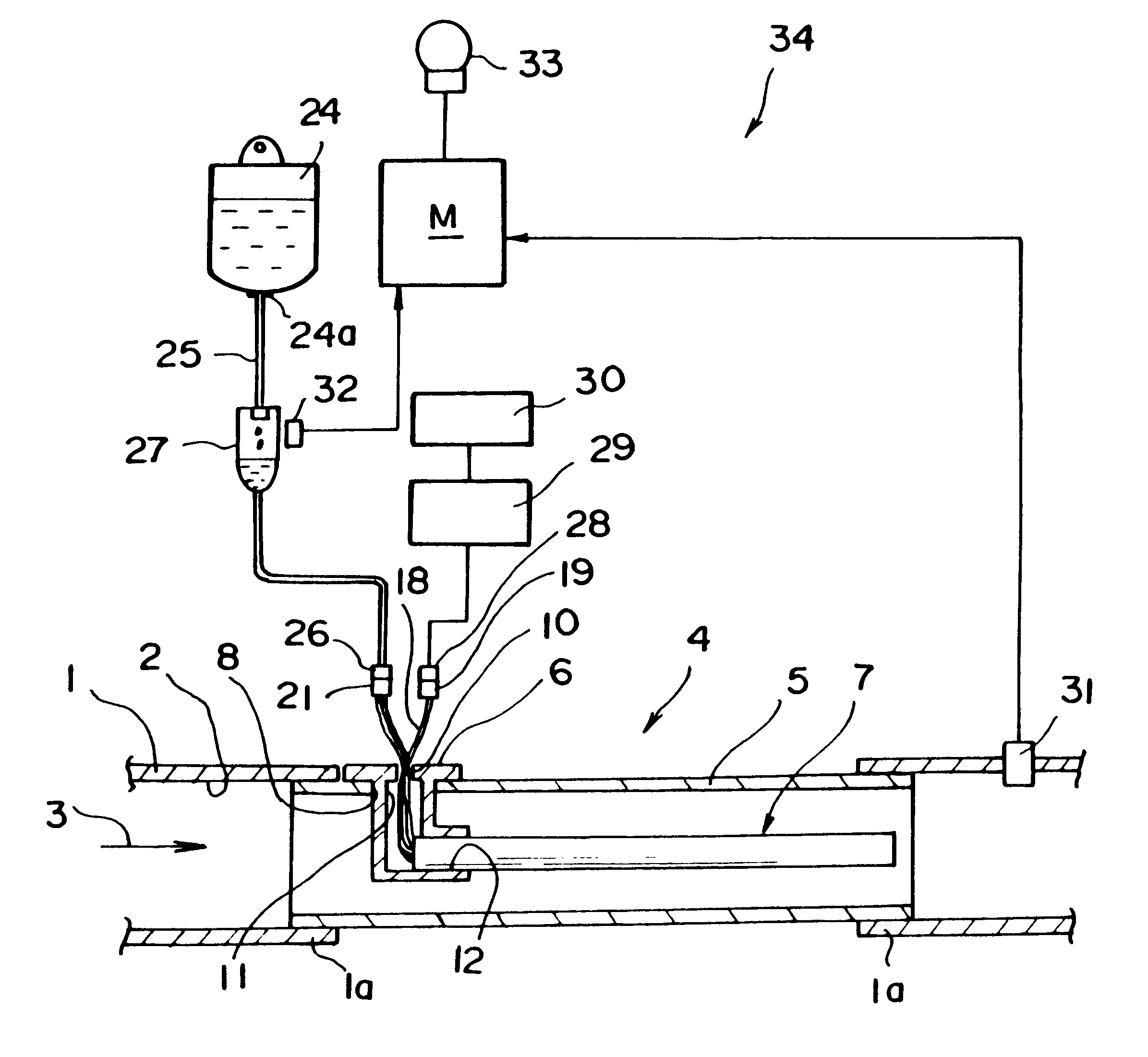
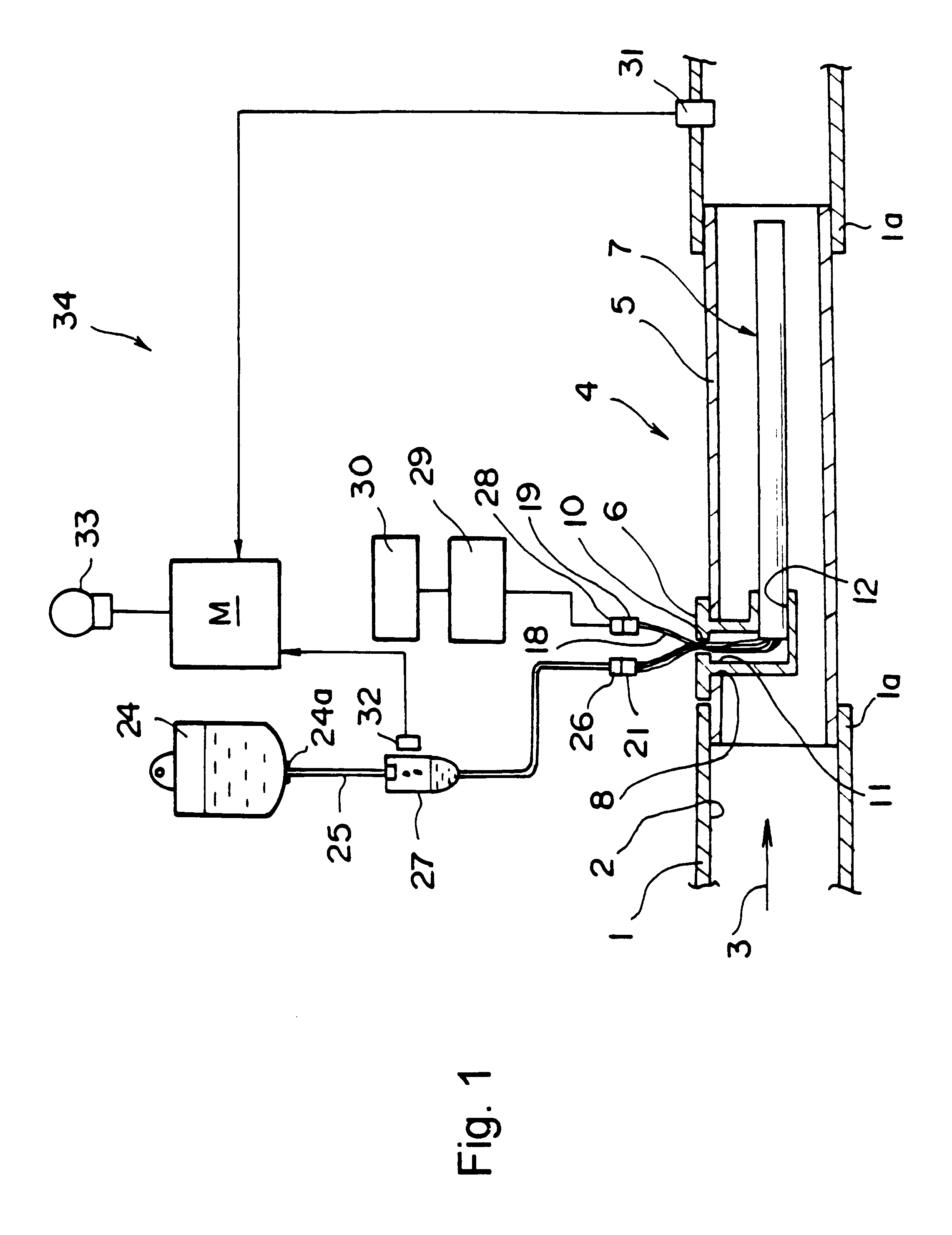
The present invention will be described by way of examples with reference to the accompanying drawings. FIGS. 1 to 7 show the humidification unit according to the present invention. As shown in FIG. 1, reference numeral 1 denotes a patient circuit in an artificial respiratory device suitable for connecting an adapter (not shown), which is connected to the lungs of a patient, to a source of breathing gas. An inner portion of patient circuit 1 constitutes an intake path 2 for the delivery of breathing gases to an airway of the patient from a supply of breathing gas, such as a pressure generator. The flow of breathing gas ill patient circuit 1 is indicated by arrow 3. The inner diameter of patient circuit 1 may be set to be in the range of, for example, from 14 mm to 16 mm of an infant patient and from 20 mm to 24 mm for an adult patient.
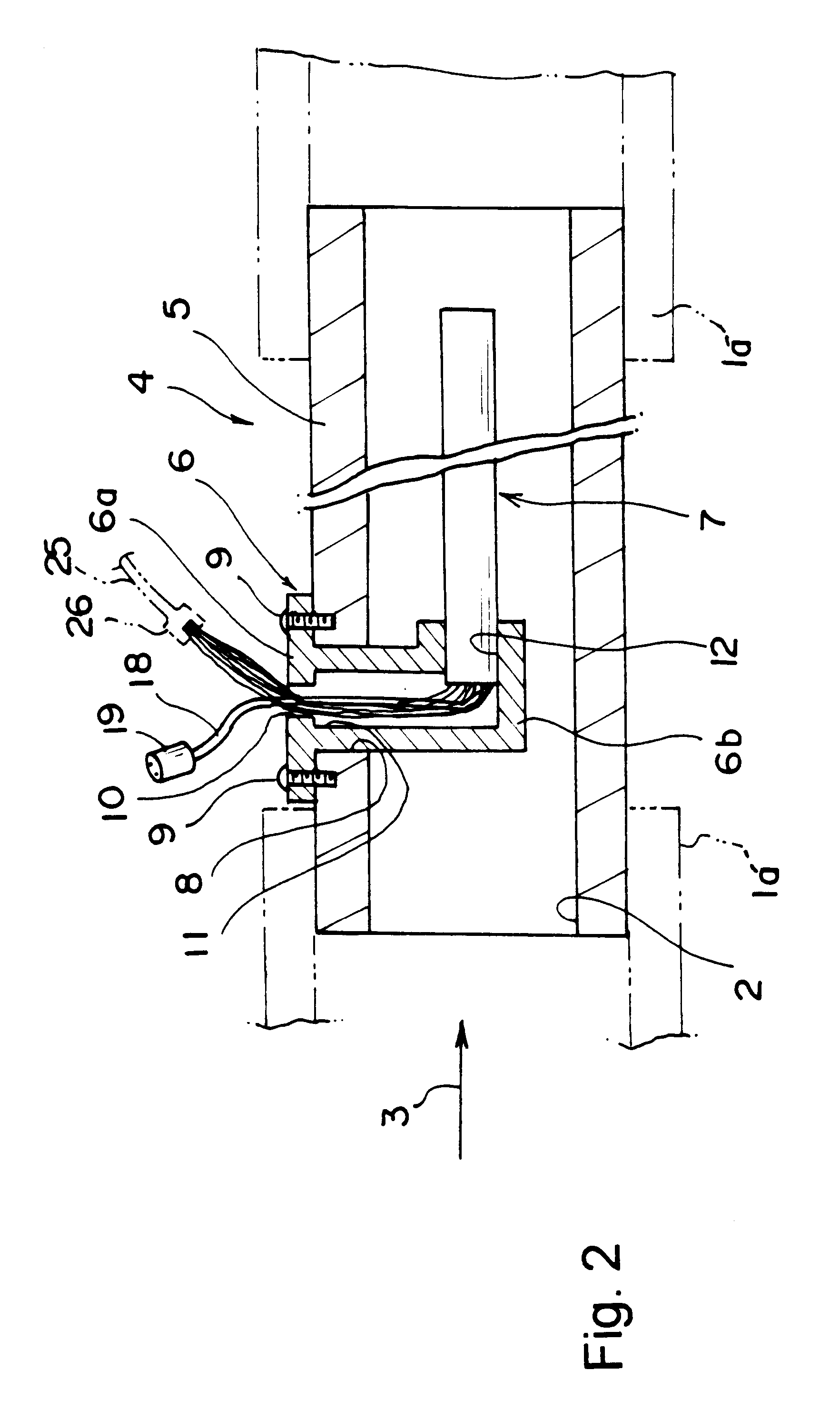
In the embodiment shown in FIGS. 1 and 2, patient circuit 1 is mounted detachably to a humidification unit 4 that is provided with a short connection ...
fourth embodiment
In the present invention, as shown in FIG. 10, the multiple hollow fiber strip 22b is wound around exothermic member 13, starting with a one end portion of the exothermic member, over the entire length thereof to the other end portion thereof and then continually turning from the other end portion thereof back to the one end portion thereof. Winding of multiple hollow fiber strip 22b around exothermic member 13 in this manner locates both end portions of multiple hollow fibers strip 22b at the one end portion of exothermic member 13 and both end portions of multiple hollow fibers strip 22b are formed with one connector 21. As a matter of course, at this time, both end portions of the multiple hollow fibers gathering 22b can be bundled together integrally and the bundled portion may be formed with one connector 21.
In the fourth embodiment of the present invention, the amount of multiple hollow fibers 14 held on exothermic member 13 can be increased, thereby improving the humidifying ...
seventh embodiment
FIG. 15 shows a humidification unit in accordance with the present invention, which is a variant of the humidification unit 4. In the humidification of unit 4 of FIG. 15, mounting flange 6 is arranged in a manner such that holding portion 6b', is disposed standing upright from flange portion 6a and one end portion of humidifying element 7 is curved at a nearly right angle with respect to the other end portion thereof. Further, one end portion of humidifying element 7 is held to holding portion 6b' by engagement therewith.
In this case, humidifying element 7 can be disposed with the other end portion thereof extending in the axial direction of connection tube 5 by mounting mounting flange 6 on connection tube 5.
FIG. 16 shows a humidification unit in accordance with an eighth embodiment of the present invention. In the eighth embodiment, connection tube 5' is a generally L-shaped tube and is disposed in such a manner that one end portion of humidifying element 7 is mounted through moun...
PUM
 Abstract
Description
Claims
Application Information