Ureteral stent system apparatus and method

a ureteral stent and system apparatus technology, applied in the field of stents, can solve the problems of occlusion, collapse, or compromise of body passages, and achieve the effects of reducing the risk of occlusion

Inactive Publication Date: 2002-05-28
APPL MEDICAL RESOURCES CORP
View PDF24 Cites 146 Cited by
  • Summary
  • Abstract
  • Description
  • Claims
  • Application Information

AI Technical Summary

Problems solved by technology

These body passages can become occluded, collapsed, or compromised from disea...

Method used


Image

  • Ureteral stent system apparatus and method
  • Ureteral stent system apparatus and method
  • Ureteral stent system apparatus and method

Examples


Embodiment Construction

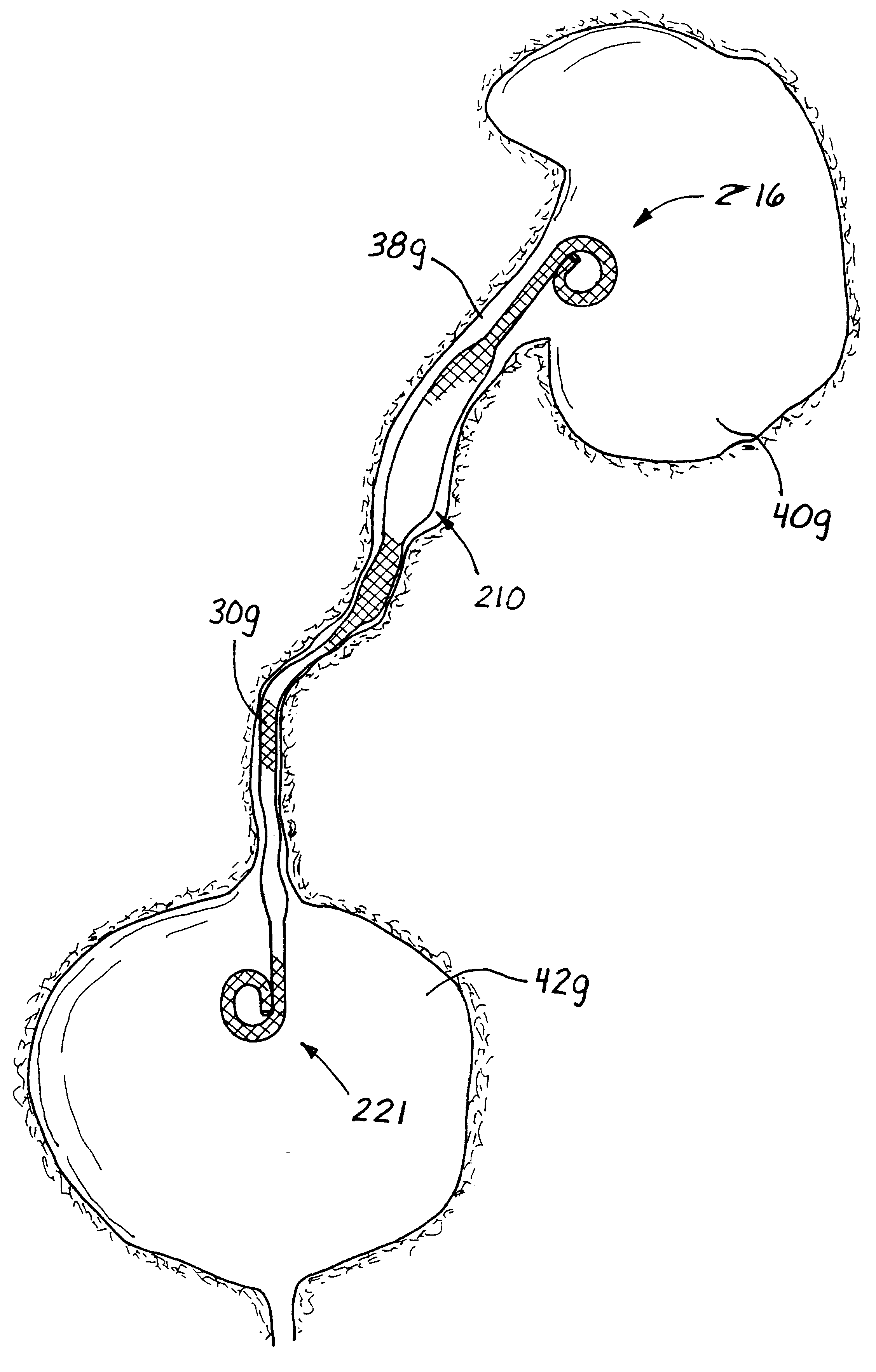
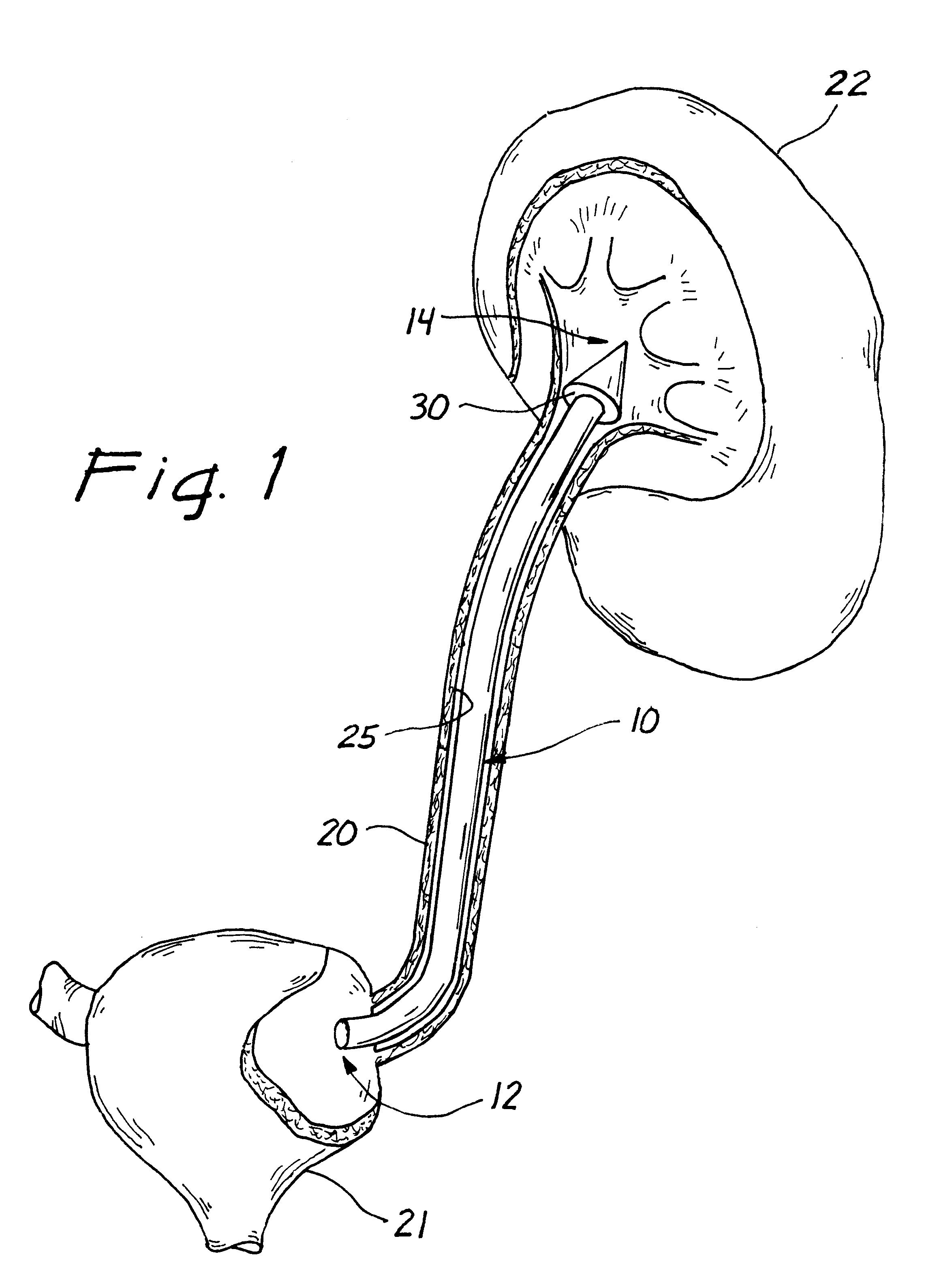
Turning to FIG. 1, a stent or prosthesis 30 according to the presently preferred embodiment is illustrated having a proximal tube end 32 and a distal tube end 34. The stent body 36 is shown within a body passage or vessel 38, such as a ureter. The stent body 36 extends within the ureter 38 between a kidney 40 and a urinary bladder 42. The stent body 36 of the present invention is sized and configured to exert a compressive force against the interior surface 45 of the body passage 38. In the presently preferred embodiment, the stent 30 comprises a retention member 48 at the distal tube end 34. The stent 30 of the embodiment shown in FIG. 1 comprises a ureteral stent, which is adapted for developing or maintaining a patent lumen in the ureter 38 between the kidney 40 and the urinary bladder 42. The stent 30 facilitates passage of fluid in, through, and around the stent body 36 from the kidney 40 to the urinary bladder 42.

The stent of the present invention preferably comprises a woven ...


PUM


Abstract

A stent having an elongate tubular configuration is formed of a plurality of elongate elements interwoven or braided to form a tubular configuration. The elements may be relatively strong and rigid, but movable relative to each other within the weave or braid in order to provide the stent with generally soft characteristics. The elements may be formed of different materials, such as an absorbent material permitting the stent to be doped with materials such as drugs and chemicals. Even the absorbency can be controlled and varied to provide a predetermined time-release of the absorbent.

Description

1. Field of the InventionThe present invention relates generally to stents for use in supporting and maintaining an open lumen within a body passage or vessel and, more particularly, to stents configurable between large and small diameters.2. Description of Related ArtTubular prosthesis, which are commonly referred to as stents, are used to reinforce or strengthen body passages or vessels. Occluded, collapsed, or compromised body passages, such as blood vessels, esophagus, tracheas, gastrointestinal tracts, bile ducts, ureters, and urethras, can all benefit from stents. These body passages can become occluded, collapsed, or compromised from disease, trauma, or from specific surgical procedures upon the wall of the body passage.Prior art stents typically comprise a length of plastic tubular material, having a number of side holes disposed along the length of the plastic tubular material. U.S. Pat. Nos. 4,913,683; 4,643,716; 5,282,784; 4,957,479; 4,931,037; and 5,364,340 describe sten...

Claims


Application Information

Patent Timeline
IPC IPC(8): A61F2/06A61F2/04A61F2/00A61F2/82A61F2/90
CPCA61F2/04A61F2/042A61F2/82A61F2/95A61M27/008A61F2/90A61F2/848A61F2002/048A61F2250/0067
Inventor HART, CHARLES C.CLAYMAN, RALPH V.BRUSTAD, JOHN R.VANDENBROEK, FRANSEWERS, RICHARD C.
Owner APPL MEDICAL RESOURCES CORP
Why Eureka
Try Eureka