
Self contained breathing apparatus

a breathing apparatus and self-contained technology, applied in the direction of audible signalling systems, operating means/releasing devices of valves, instruments, etc., can solve the problems of adding to the cost of two first-stage regulators and a pair of transfer valves, and achieve the effect of more economical manufacture and us

Inactive Publication Date: 2002-06-11
SCOTT TECH INC
View PDF20 Cites 40 Cited by
  • Summary
  • Abstract
  • Description
  • Claims
  • Application Information

AI Technical Summary

Benefits of technology

It is a further object of the present invention to provide a self contained breathing apparatus which provides a user with an indication that an air supply is approaching depletion.
It is a further object of the present invention to provide a self contained breathing apparatus that provides a user with multiple indications of the impending depletion of an air supply.
It is a further object of the present invention to provide a self contained breathing apparatus that is more economical to manufacture and use.
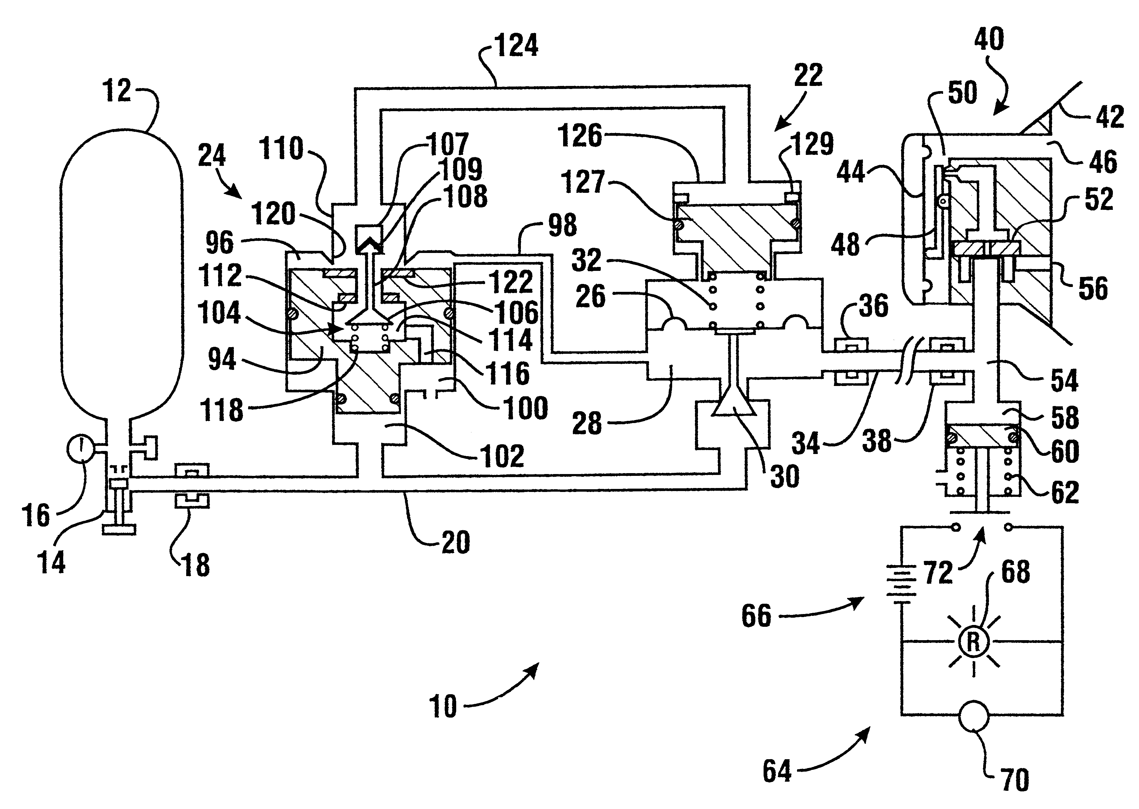
The air supply to the second stage regulator is in fluid communication with a sensor which may be adjacent to the face mask or in another location. The increase in pressure is detected by the sensor which actuates an alarm circuit. The alarm circuit may include visual alarms such as lights, as well as audio or other alarms which provide the user with an indication of the impending depletion of the air supply. In addition, the increased pressure may also be used to actuate a whistle or vibrator of the conventional type in the mask or other location. These multiple alarm indications provide greater assurance that the user will be aware of the impending depletion of the air supply even though the user is working in a noisy or other difficult environment.

Problems solved by technology

While my prior system is highly reliable, the use of two first stage regulators and a pair of transfer valves adds to its cost.

Method used


Image

  • Self contained breathing apparatus
  • Self contained breathing apparatus
  • Self contained breathing apparatus

Examples


Embodiment Construction

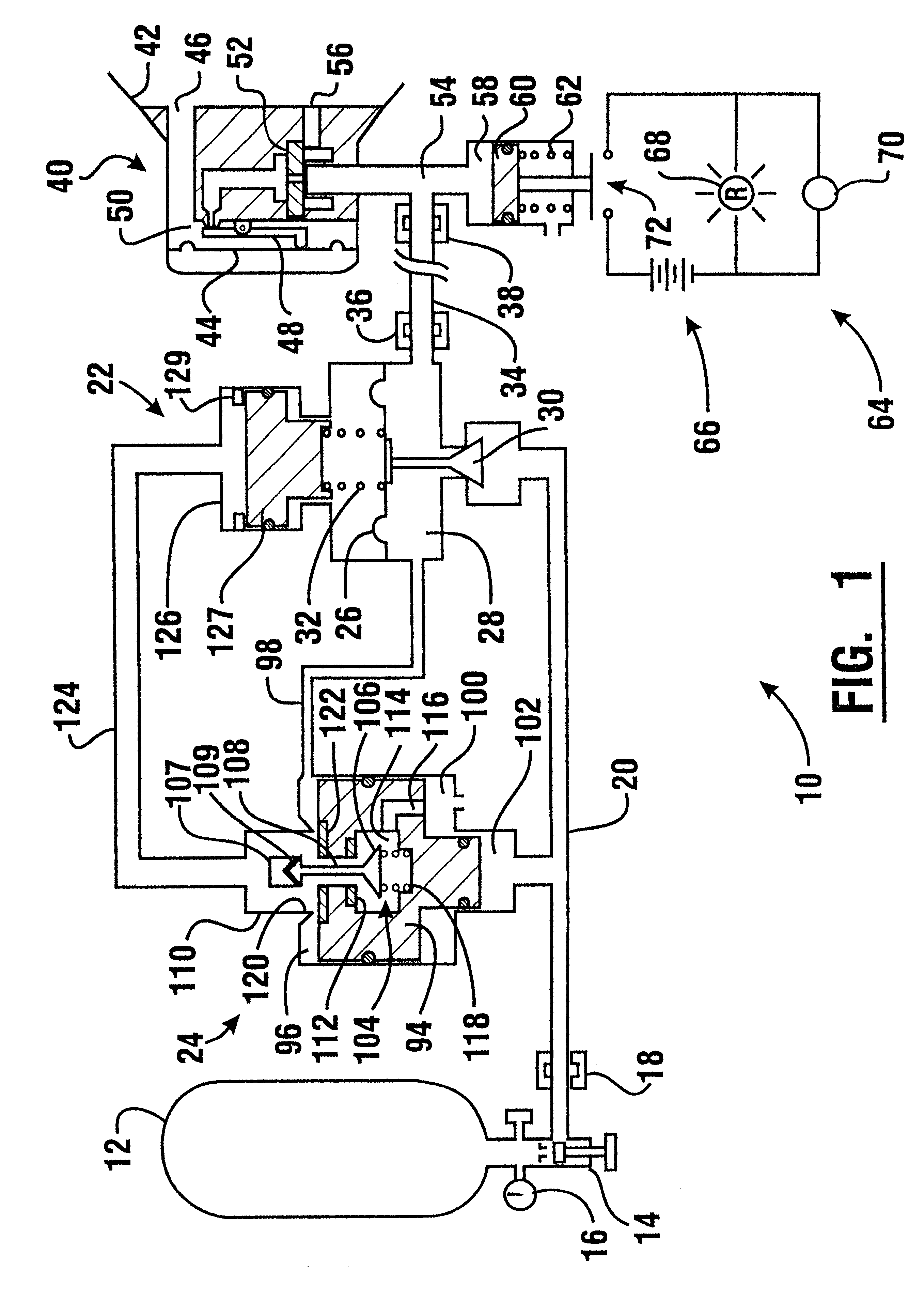
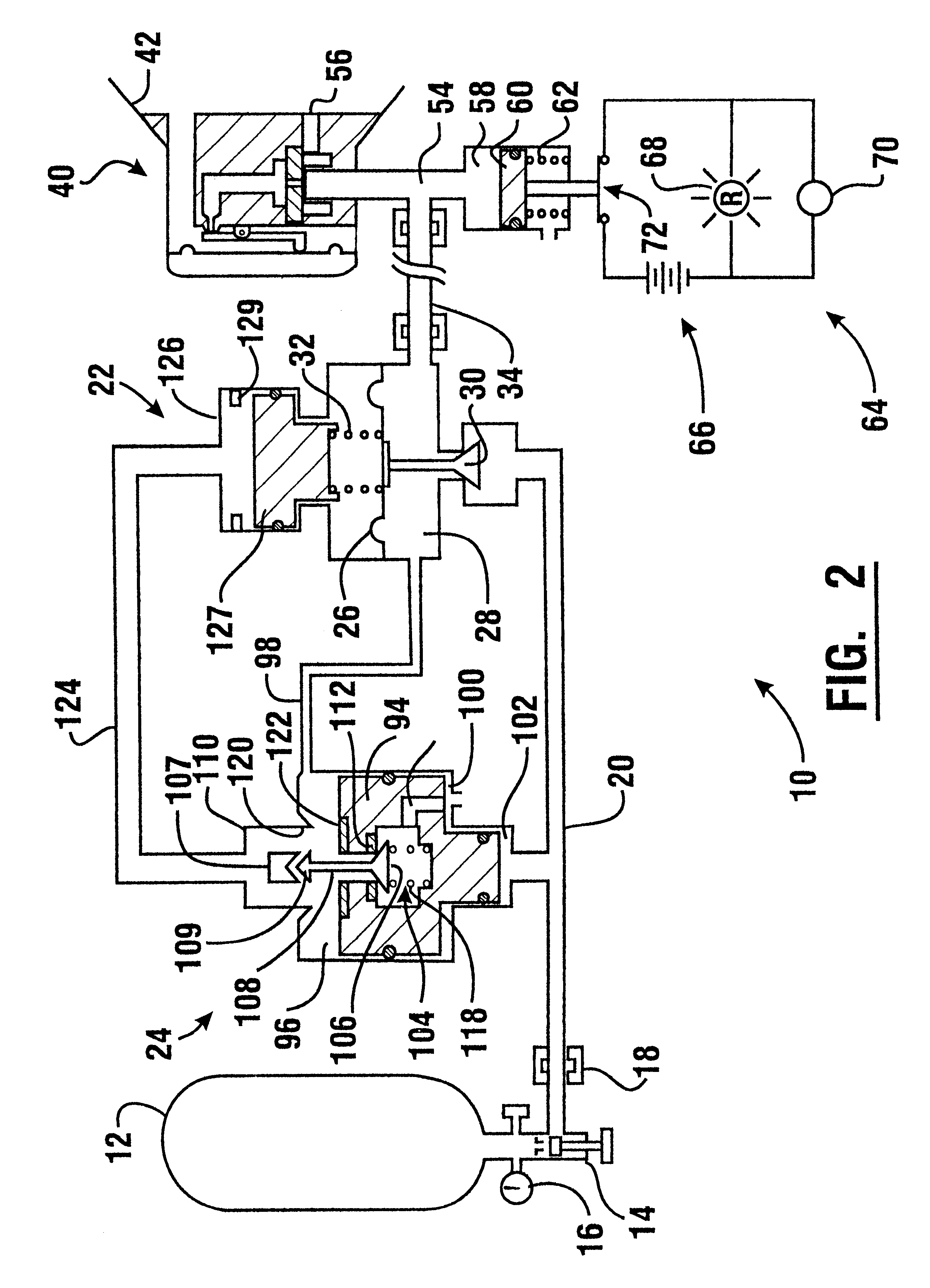
Referring now to the drawings and particularly to FIG. 1, there is shown therein a first embodiment of a self contained breathing apparatus of the present invention generally indicated 10. The apparatus includes a pressure vessel 12 or other source which provides a supply of breathing air. In one preferred form of the invention the pressure vessel may be of the type that initially holds air at a pressure of about 316.4 Kg. / sq.cm (4500 PSIG). The pressure vessel includes a conventional outlet valve 14 and a pressure gauge 16. The pressure vessel 12 is preferably coupled to the remainder of the system through a releasable coupling 18.

Coupling 18 is connected to a supply conduit, schematically indicated 20. Supply conduit 20 is in fluid communication with a first stage pressure regulator 22. Supply conduit 20 is also in fluid communication with a step up valve 24.

First stage regulator 22 in the embodiment shown is a single stage regulator. It includes a diaphragm 26 which serves as a m...


PUM


Abstract

A self contained breathing apparatus includes a pressure vessel which holds a supply of breathing air. The pressure vessel is in fluid communication through a first stage pressure regulator with a second stage breathing regulator. The breathing regulator is operatively connected to a user face mask. When the pressure available in the supply is at a suitable pressure, the pressure regulator provides pressure to breathing regulator at a first pressure. When the pressure in the supply falls to a value indicative of impending depletion of the air supply, a transfer piston in a step up vale shifts. A change in condition of the step up valve causes a step up piston to increase the output pressure from regulator. This increased pressure moves a sensing piston and causes indicating devices in an alarm circuit to be activated. In alternative embodiments, an electronic alarm module may be used.

Description

This invention relates to a self contained breathing apparatus.Specifically this invention relates to a self contained breathing apparatus that provides an indication to a user that a supply of air is approaching depletion.Self contained breathing apparatus are known in the prior art. Such devices are commonly used by individuals who are required to perform activities in noxious atmospheres. Individuals who commonly use self contained breathing apparatus include fire fighters and persons involved in cleaning up chemical spills.A self contained breathing apparatus generally includes a supply of pressurized breathing air. The breathing air is maintained in a vessel at a relatively high pressure. Air flows from the pressure vessel to a first stage regulator which reduces the pressure from the high pressure within the vessel to a lower pressure. Air from the primary regulator is communicated to a second stage regulator. The second stage regulator is generally in communication with a fac...

Claims


Application Information

Patent Timeline
IPC IPC(8): A62B7/00A62B7/02A62B9/00
CPCA62B9/00A62B7/02
Inventor GIORGINI, EUGENE
Owner SCOTT TECH INC
Learn More