Apparatus and method to reduce power amplifier noise generation in a multiplexed communication system

a communication system and power amplifier technology, applied in secret communication, digital transmission, baseband system details, etc., can solve the problems of affecting the performance of the communication system, noise introduced by the rapid, interference with the detection and demodulation of the transmitted signal,

Inactive Publication Date: 2002-06-11
MICROSEMI SEMICON U S
View PDF3 Cites 16 Cited by
  • Summary
  • Abstract
  • Description
  • Claims
  • Application Information

AI Technical Summary

Problems solved by technology

One of the problems that arises with a multiplexing mode of operation is the noise introduced by the rapid switching from a power-off mode to a power-on mode.
The noise interferes with the detection and demodulation of the transmitted signal.
These energy spikes result in interfering noise energy that degrades the performance of the communication system in the broadcast band for which the communication system 10 is intended.
The ramped transmitted signal reduces the noise resulting from abrupt leading edge of transmitted signal, but results in diminished amplitude of the transmitted signal during the initial enabling of the power amplifier.

Method used


Image

  • Apparatus and method to reduce power amplifier noise generation in a multiplexed communication system
  • Apparatus and method to reduce power amplifier noise generation in a multiplexed communication system
  • Apparatus and method to reduce power amplifier noise generation in a multiplexed communication system

Examples


Embodiment Construction

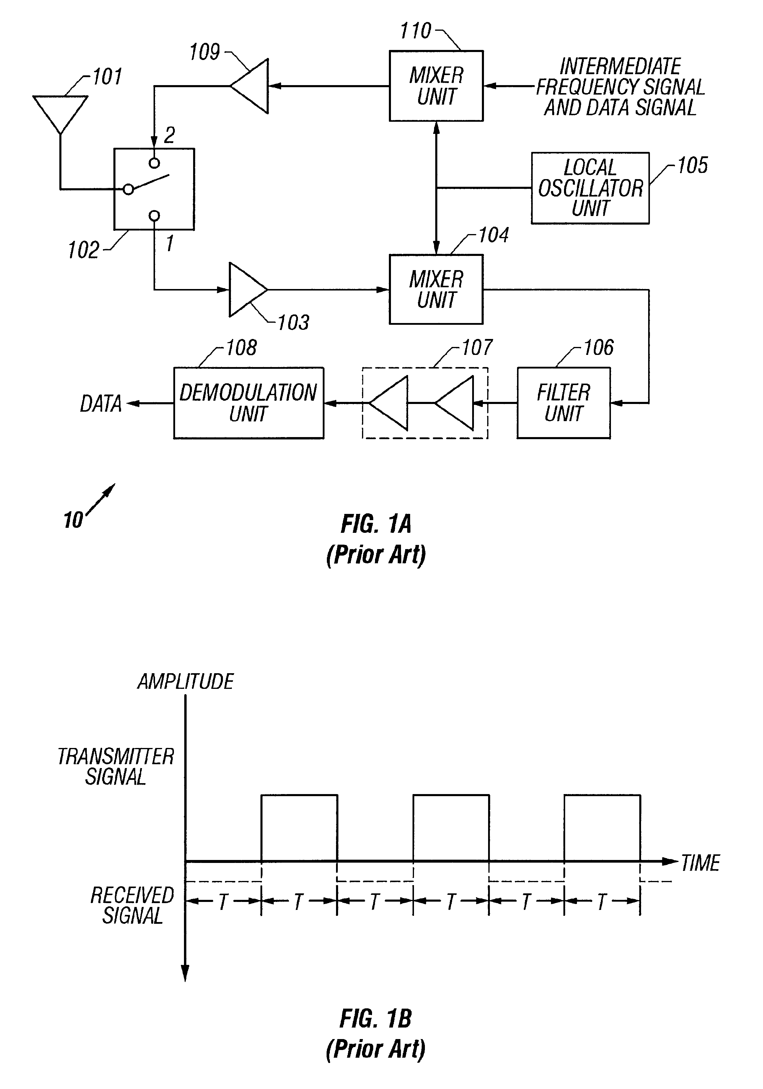
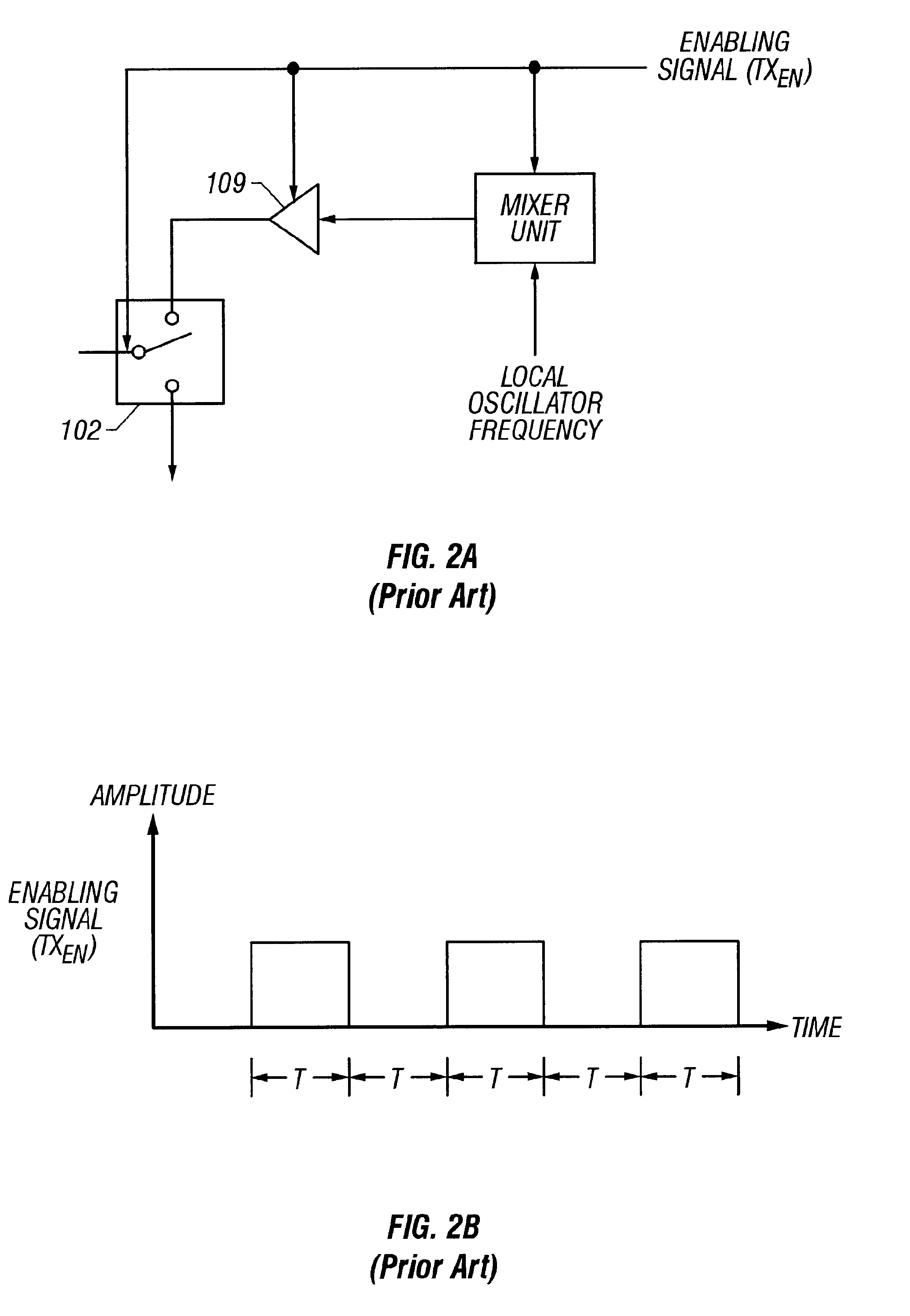
FIG. 1A, FIG. 1B, FIG. 2A, FIG. 2B, FIG. 3A and FIG. 3B have been described in relationship to the prior art.

Referring to FIG. 4A, a graph illustrating the enabling signal for the power amplifier (and consequently, along with the switch 102, the transmission of a signal) is shown. Instead of an abrupt in the leading edge of the enabling signal such as is shown in FIG. 2B, the enabling signal for the power amplifier 109 has a ramped leading edge. The period T shown in FIG. 4A refers to the time that the switch 102 of FIG. 1A is in the power transmission mode. Referring next to FIG. 4B, the envelope 45 of the transmitted carrier frequency signal (i.e., from the output of power amplifier 109) has a ramped leading edge as a result of the ramped enabling voltage shown in FIG. 4A. The envelope of the transmitted signal will be modulated by information signal 46. The information signal 46, separated in FIG. 4B from the carrier signal 45 for purposes of illustration, has two portions, the p...


PUM


Abstract

In order to reduce the noise components in a multiplexed communication system, noise components generally referred to as splatter that from the rapid transition between the transmitting state and the non-transmitting state, this power transition in the transmitted signal is provided with a ramped envelope. In the preferred embodiment, the ramped power transition is the result of a ramped enabling signal applied to the power amplifier generating the transmitted signal. The use of a ramped power transition reduces the noise introduced as a result of an abrupt power transition. In addition, the transmitted signal is provided with a preamble so that no data is transmitted during the transition period.

Description

1. Field of the InventionThis invention relates generally to multiplexed communication systems and, more particularly, to noise generated by rapid change in transmitted power during the interval reserved for the transmission of information. This noise is generally referred to as splatter.2. Description of the Related ArtA typical communication system 10 using time division multiplex techniques is shown in FIG. 1A. An antenna 101 is coupled to a two position switch 102. When the switch 102 is coupled to a first terminal, the signal received by the antenna 101 is applied to low noise amplifier 103. The output signal from the low noise amplifier 103 is applied to mixer unit 104. The mixer unit 104 also receives a signal from the local oscillator unit 105. The signals from the low noise amplifier 103 and the local oscillator unit 105 are combined in mixer unit 104 and applied to filter unit 106. The filtered signal from filter unit 106 is applied to an IF (intermediate frequency) unit 1...

Claims


Application Information

Patent Timeline
Patent Type & Authority Patents(United States)
IPC IPC(8): H04B1/48H04B1/04H04B1/44
CPCH04B1/48H04B1/0475
Inventor BELL, EDDY KENTJANESCH, STEPHEN T.
Owner MICROSEMI SEMICON U S
Why Eureka
Try Eureka