Surgical suction probe system with an easily cleaned internal filter

Inactive Publication Date: 2002-06-18
MEDECON
View PDF26 Cites 50 Cited by
  • Summary
  • Abstract
  • Description
  • Claims
  • Application Information

AI Technical Summary

Problems solved by technology

Once removed, the filter medium cannot be reattached to the supporting structure.
The process of disassembly, wiping, and reassembly is relatively time consuming, and must often be performed several times during a surgical procedure.
A lack o

Method used


Image

  • Surgical suction probe system with an easily cleaned internal filter
  • Surgical suction probe system with an easily cleaned internal filter
  • Surgical suction probe system with an easily cleaned internal filter

Examples


Embodiment Construction

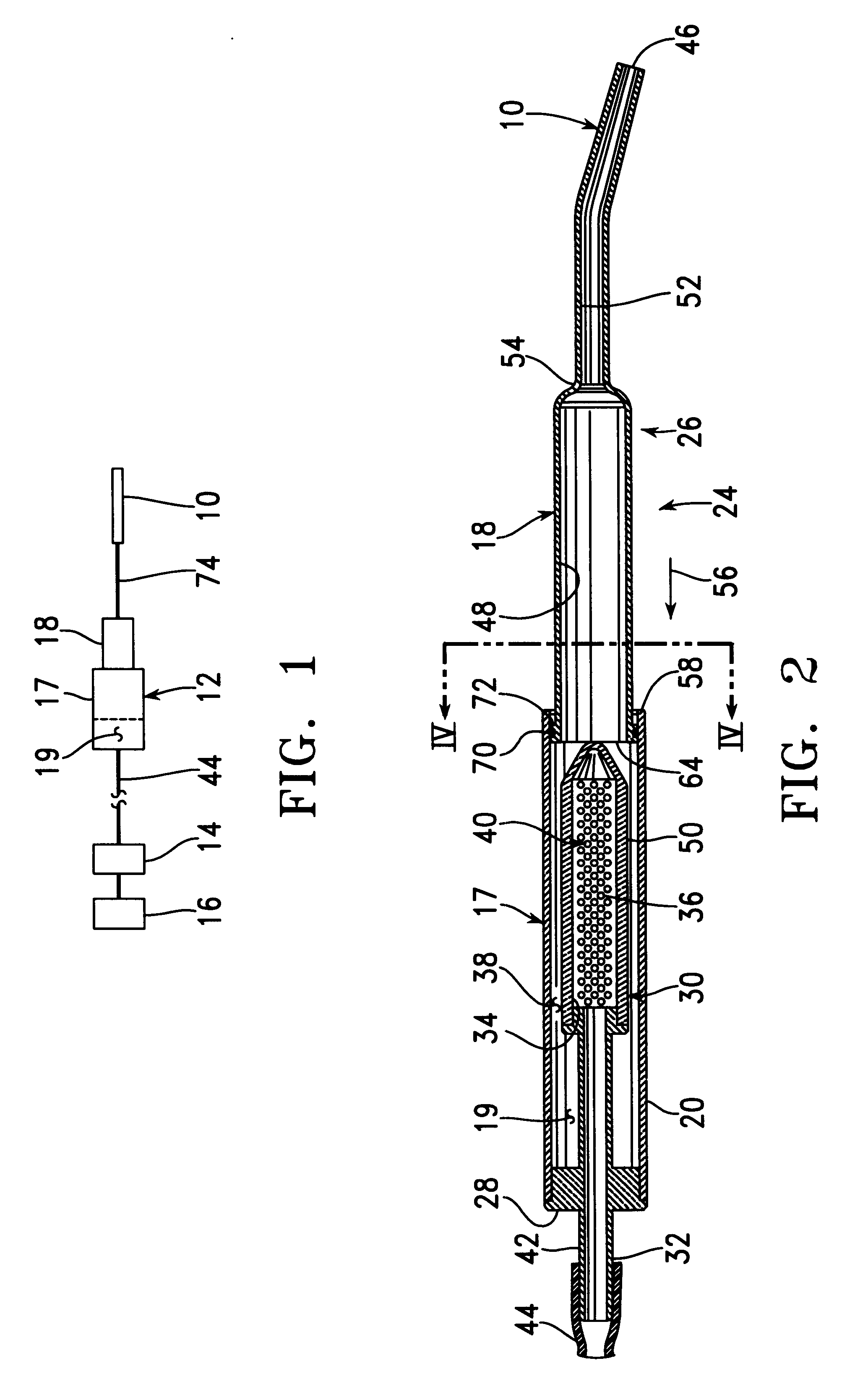
FIG. 1 is a schematic view of a surgical suction system built in accordance with the present invention for removing debris from a surgical site, including a probe tip 10, a first filter 12, a second filter 14, and a vacuum source 16. The surgical suction system may be partly composed of a central vacuum system within the hospital, with the probe tip 10 and the first filter 12 being disposed within an operating room, and with the second filter 14 and the vacuum source 16 being disposed in another part of the hospital in the form of a central vacuum system. In accordance with the present invention, the first filter 12 includes a filter section 17, a slider 18, and a reservoir 19. When the slider 18 is moved into the filter section 16, debris held on a surface of a filter surface (not shown) within the filter section 17 is scraped off the filter surface and deposited within the reservoir 19.

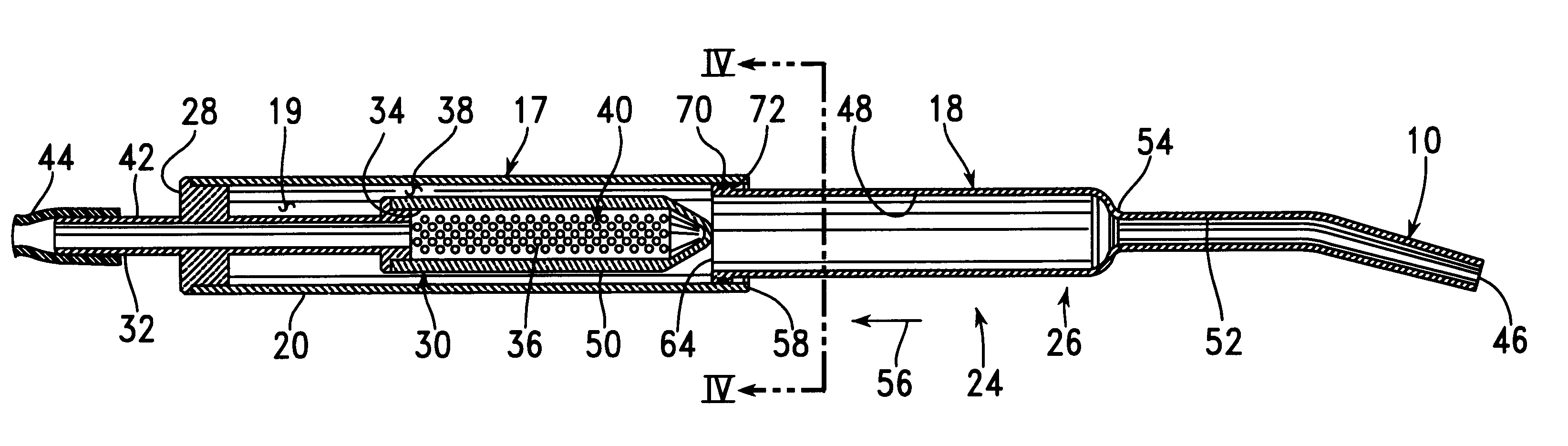
FIG. 2 is a longitudinal cross-sectional view of a surgical suction probe 24 built in accordance...


PUM

PropertyMeasurementUnit
Transparencyaaaaaaaaaa

Abstract

A suction probe system for cleaning debris from a surgical site includes a probe tip, a filter unit in fluid communication with the probe tip, and a suction source in fluid communication with the filter unit. The filter unit includes a cylindrical filter having an inner chamber attached to the suction source and an outer surface which accumulates debris particles too large to pass through holes within the cylindrical filter. The filter unit also includes a slider having an open-ended cylinder which is slid along the outside of the cylindrical filter to remove accumulated debris particles and to push these debris particles into a reservoir within the filter unit. The slider and the probe tip can be made integral parts of a single sliding member.

Description

BACKGROUND INFORMATION1. Field of InventionThis invention relates to a probe forming a part of a surgical suction system for the removal of debris from a surgical site, and, more particularly, to such a probe including an internal filter for removing and holding larger pieces of such debris from waste slurry flowing through the probe.2. Description of the Related ArtThe patent literature describes a number of suction probes for use in surgical suction systems to remove debris from a surgical site, with the probe including or being associated with an internal filter for removing and holding the larger pieces of waste slurry flowing through the probe. Such a suction probe has an inlet large enough to permit the entrance of debris particles too large to be handled reliably through the remaining portion of the suction system, such as the conduit leading to a suction source. These particles are trapped within the internal filter. Each such suction probe is separable into two pieces so th...

Claims


Application Information

Patent Timeline
IPC IPC(8): A61M1/00
CPCA61M1/0039A61M1/008Y10S604/902A61M1/0056A61M1/76A61M1/79A61M1/84
Inventor HAJIANPOUR, MOHAMMED ALI
Owner MEDECON
Why Eureka
Try Eureka