Stereo image display unit

a display unit and image technology, applied in image enhancement, color signal processing circuits, instruments, etc., can solve the problems of high unit price, inconvenient use, and inability to adjust the focus,

Inactive Publication Date: 2002-06-25
OLYMPUS OPTICAL CO LTD
View PDF16 Cites 86 Cited by
  • Summary
  • Abstract
  • Description
  • Claims
  • Application Information

AI Technical Summary

Problems solved by technology

Therefore, a state of inconsistency between the mergence of the observer's eyeballs and the focus control may arise.
This means that a glance motion

Method used


Image

  • Stereo image display unit
  • Stereo image display unit
  • Stereo image display unit

Examples


first embodiment

In the first embodiment, a local image area with a motion vector different from that of the remainder of the display surface is detected, depth (distance) of the image in the detected image area is obtained, and glance distance and vergence distance in a stereo image observation are controlled to be coincident with each other. In this embodiment, a left and a right image with a parallax between them are collectively referred to as a stereo image.

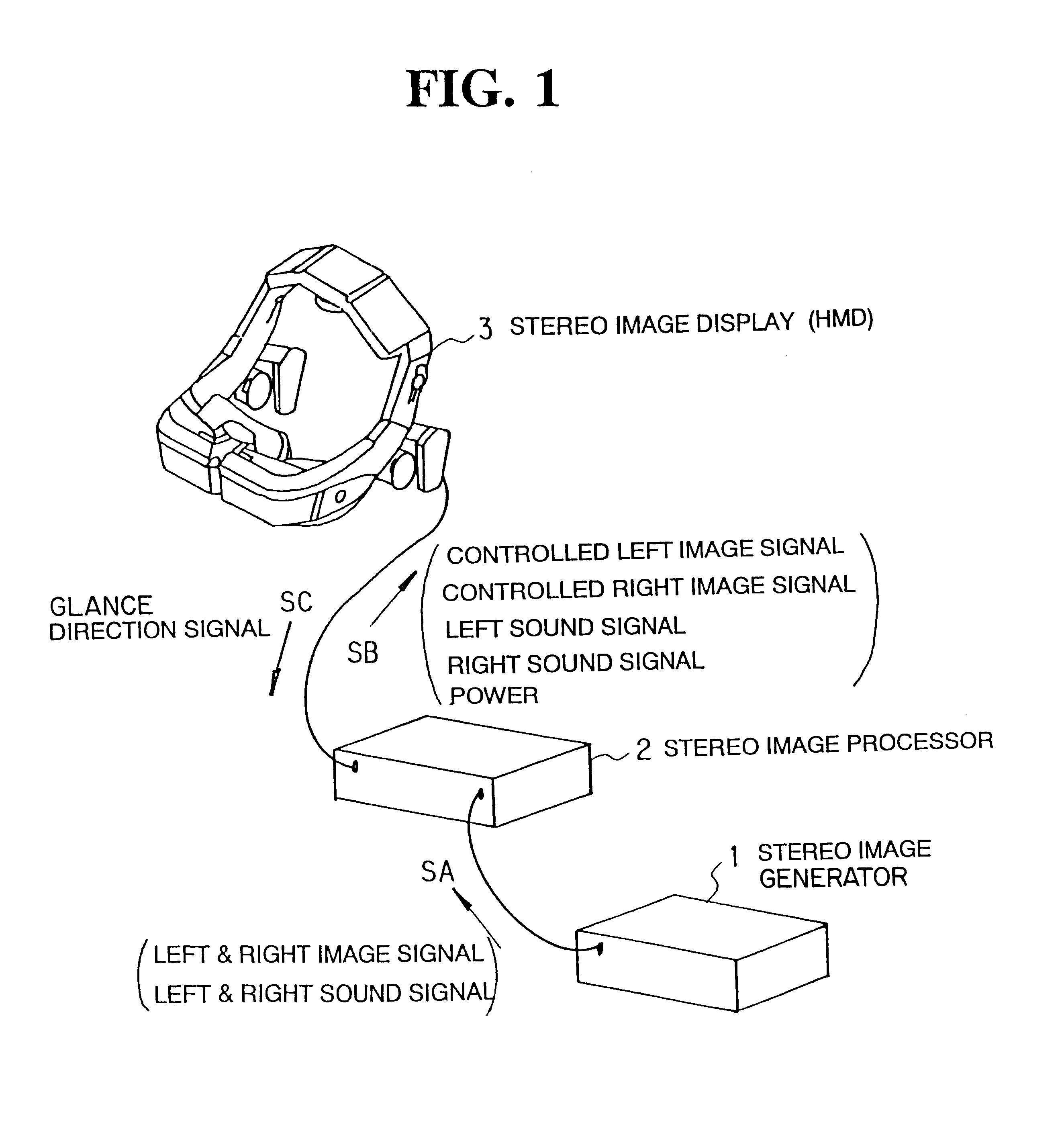
FIG. 1 is a view outlining the first embodiment of the stereo image display unit according to the present invention. The stereo image display unit illustrated in FIG. 1 comprises a stereo image generator 1, a stereo image processor 2 and a stereo image display 3. The stereo image generator 1 generates a stereo image signal SA (i.e., a left and a right image signals), and provides the signal together with a left and a right speech signal. The stereo image generator may be such an image generator as a video playback unit, a stereo image signal...

second embodiment

Now the present invention, which detects left and right image motion vectors, will be described.

In the first embodiment, motion vectors were obtained with only left or right images. The second embodiment is a modification of the first embodiment, and adapted to obtain motion vectors with both left and right images.

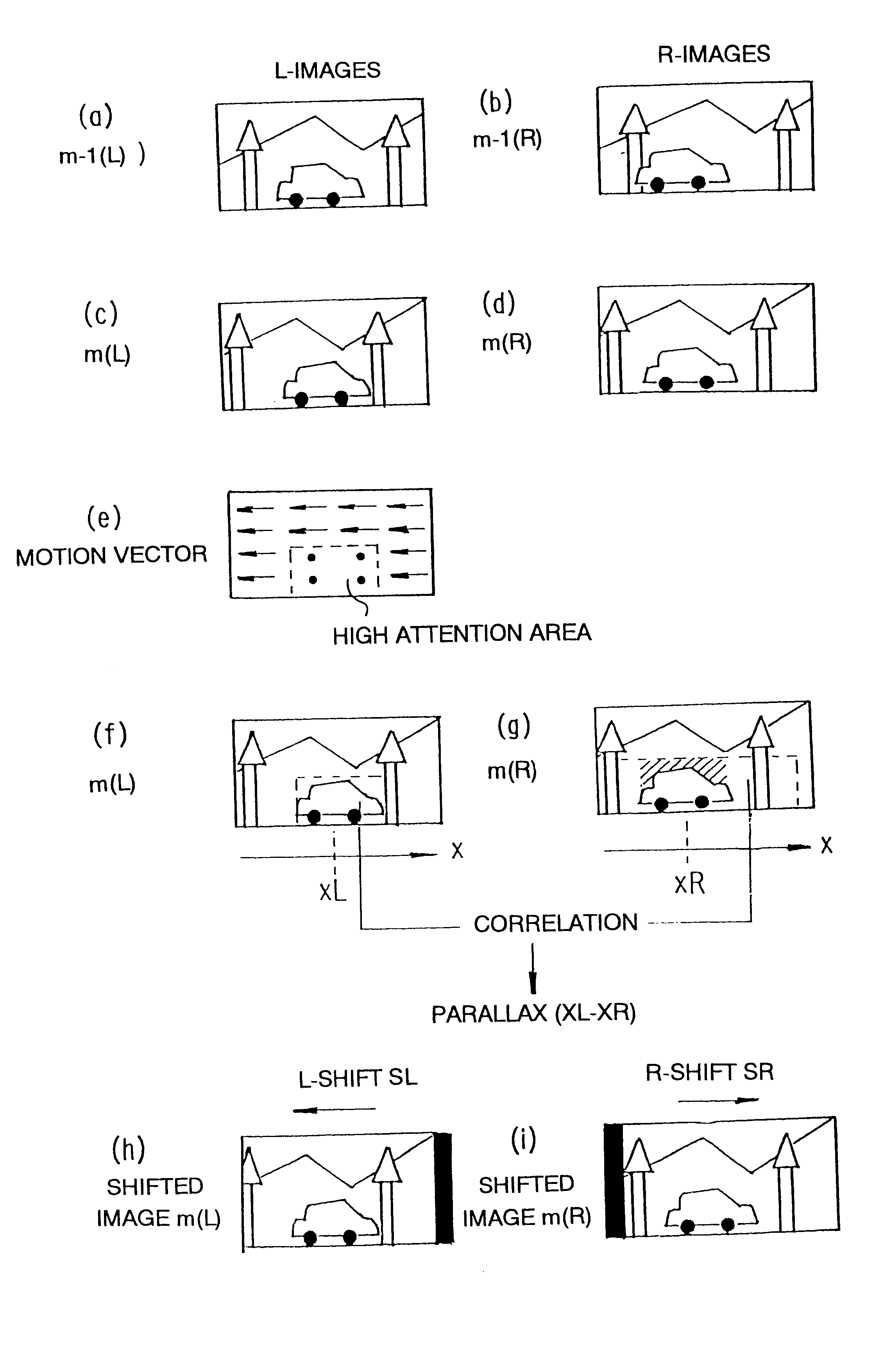
For example, as shown in FIGS. 15(a) to 15(j) with left images as shown in FIGS. 15(a) and 15(c) motion vectors as shown in FIG. 15(e) are obtained, and with right images as shown in FIGS. (b) and (d) motion vectors as shown in FIG. 15(f) are obtained. Then, respective high attention center presumable areas as shown in FIGS. 15(g) and 15(h) are determined.

Then, the center x coordinates xL and xR of the presumable attention center areas are obtained. The difference (xL-xR) between the x coordinates xL and xR is determined to be the parallax. Thus, in the second embodiment no correlation calculation is made.

FIG. 16 is a block diagram showing the internal construction of the ...

third embodiment

The third embodiment is also a modification of the first embodiment, and effective for field (or frame) sequential stereo image. Specifically, in this embodiment the parallax is obtained by detecting motion vectors between left and right images at different time instants and determining a parallax based on a high attention center presumability.

FIG. 17 is a flow chart illustrating the operation in the third embodiment. The operation will now be described in connection with an example of image processing shown in FIGS. 18(a) to 18(g). In this embodiment, left and right image frames are received alternately, such as right image frame m-1(R), left image frame m(L) and right image frame m+1(R) . . . as shown in FIGS. 18(a), 18(b) and 18(c).

(Step S11)

The left image frame m(L) is received.

(Step S12)

A motion vector m of the left image frame m(L) with respect to the right image frame m-1(R) for each block. That is, a motion vector is obtained by comparing adjacent image fields (i.e., compari...


PUM


Abstract

Input means (31,32,33) receives signals representing stereo image. Image change detection means (36) detects changes with time in stereo image represented by the signals received from the input means. High attention center presumable area determination means (37) determines a peculiar local area of a displayed image area to be an observer's high attention center presumable area according to a result of detection by the image change detection means. Depth detection means (38,39) obtains information representing the depth of the image in the particular local area specified by the high attention center presumable area determination means. Depth control means (40) controls a quantity concerning the depth of stereo image represented by the signals received form the input means according to the depth information received form the depth detection means. Output means (41,42) outputs signals representing stereo image, with the quantity concerning the depth having been controlled by the depth control means, as stereo image signals to be displayed on stereo image display means.

Description

BACKGROUND OF INVENTIONThe present invention relates to stereo image display units for stereo image display according to a stereo image signal provided by input means after image depth control.Various stereo observation displays for displaying image for stereo observation have been proposed.In a prior art stereo observation display, the depth position of display surfaces and the merging depth position are not coincident. Therefore, a state of inconsistency between the mergence of the observer's eyeballs and the focus control may arise. When the inconsistency is increased, a human can no longer perceive a stereo image as a single image.Several means for solving this problem have been proposed. Japanese Laid-Open Patent Publication No. 3-292093 discloses means for detecting an observer's attention center using a glance motion detector and varying the parallax by moving lens according to depth information at the attention center. This controls "depth position of display surfaces" such ...

Claims


Application Information

Patent Timeline
IPC IPC(8): G02B27/01G02B27/22H04N13/00H04N5/74H04N5/14H04N13/04H04N13/02H04N15/00
CPCG02B27/017H04N13/0014H04N13/0051H04N13/044H04N13/0484G06T7/2006G06T7/2086G02B27/2235G06T2207/10021H04N5/145H04N5/7491H04N13/0003H04N13/0055H04N13/0289H04N13/0468H04N2013/0081H04N2013/0085H04N2013/0096G06T7/215G06T7/285H04N13/289H04N13/167H04N13/344H04N13/189H04N13/117H04N13/10H04N13/366H04N13/383G02B30/35
Inventor TABATA, SEIICHIRO
Owner OLYMPUS OPTICAL CO LTD
Why Eureka
Try Eureka