Self-flaring plastic fittings

a self-flaring, plastic technology, applied in the direction of fluid pressure sealing joints, hose connections, mechanical equipment, etc., can solve the problems of metal contamination of conveyed fluids, time and cost added to the overall tubing/fitting assembly process, etc., to achieve the effect of convenient grasping and handling

Inactive Publication Date: 2002-07-02
FLUO ROWARE INC
View PDF33 Cites 62 Cited by
  • Summary
  • Abstract
  • Description
  • Claims
  • Application Information

AI Technical Summary

Benefits of technology

The groove engaging device of the fitting nut may be unitary with the fitting nut or may be distinct therefrom. In the case of a unitary configuration, the groove engaging device preferably comprises an annular collar. In the case of a distinct configuration, the groove engaging device is preferably in the form of a retaining ring. Both fitting body and fitting nut are preferably provided with features for easier grasping and handling, e.g., fitting body is preferably provided with one or more planar surfaces for grasping with a tool while fitting nut is preferably provided with a plurality of winged extensions or knurled or ribbed surfaces for easier grasping and hand assembly. The tapered nose section of fitting the body is preferably of a shortened configuration requiring a minimal flare in the tubing. And, the fitting nut is preferably provided with an intermediate collar with a pinching extension that helps to pinch the formed flare of the tubing against the tapered nose section of the fitting body.

Problems solved by technology

However, in certain industries, the fluids conveyed may attack metal components and the metal can contaminate the conveyed fluids, i.e., the semiconductor processing industry.
This step of heating to a temperature sufficient such that the tubing may be permanently deformed and shaping the tubing prior to assembly with the fitting adds time and cost to the overall tubing / fitting assembly process.

Method used


Image

  • Self-flaring plastic fittings
  • Self-flaring plastic fittings
  • Self-flaring plastic fittings

Examples


Embodiment Construction

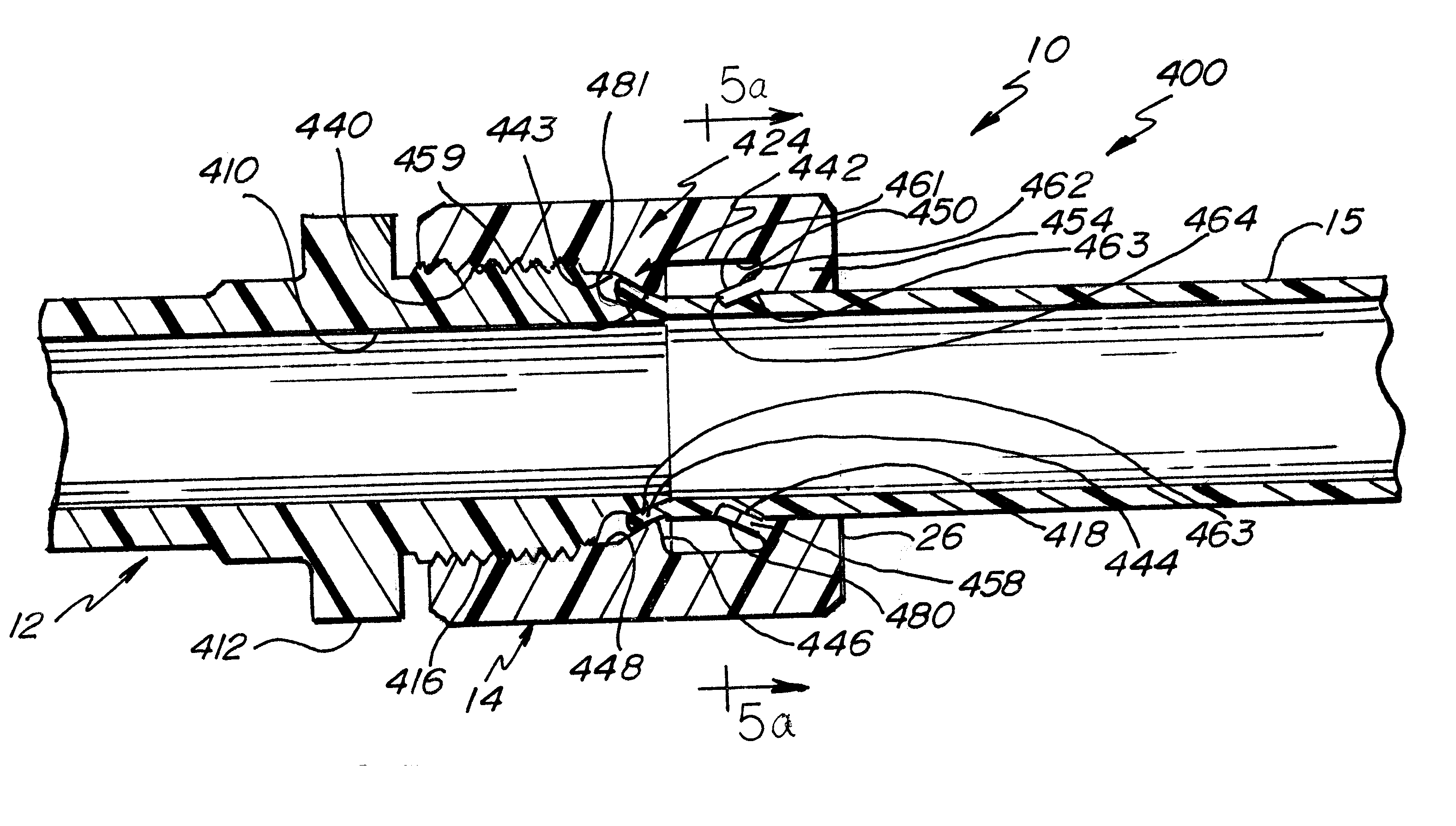
Each embodiment of the self-flaring fittings of the present invention described herein provides for quicker assembly of fittings to tubing by eliminating the need for prior heating and shaping of the tubing, i.e., to form a flared shape for connecting to the tubing, and by providing a fitting that can manually, quickly, and easily be screwed onto the tubing to form an effective seal. The quick assembly of the self-flaring fitting to tubing is, at least in part, effected by virtue of the short flare of the tubing that is needed and by the reduced number of threads that are necessary to achieve this short flare.

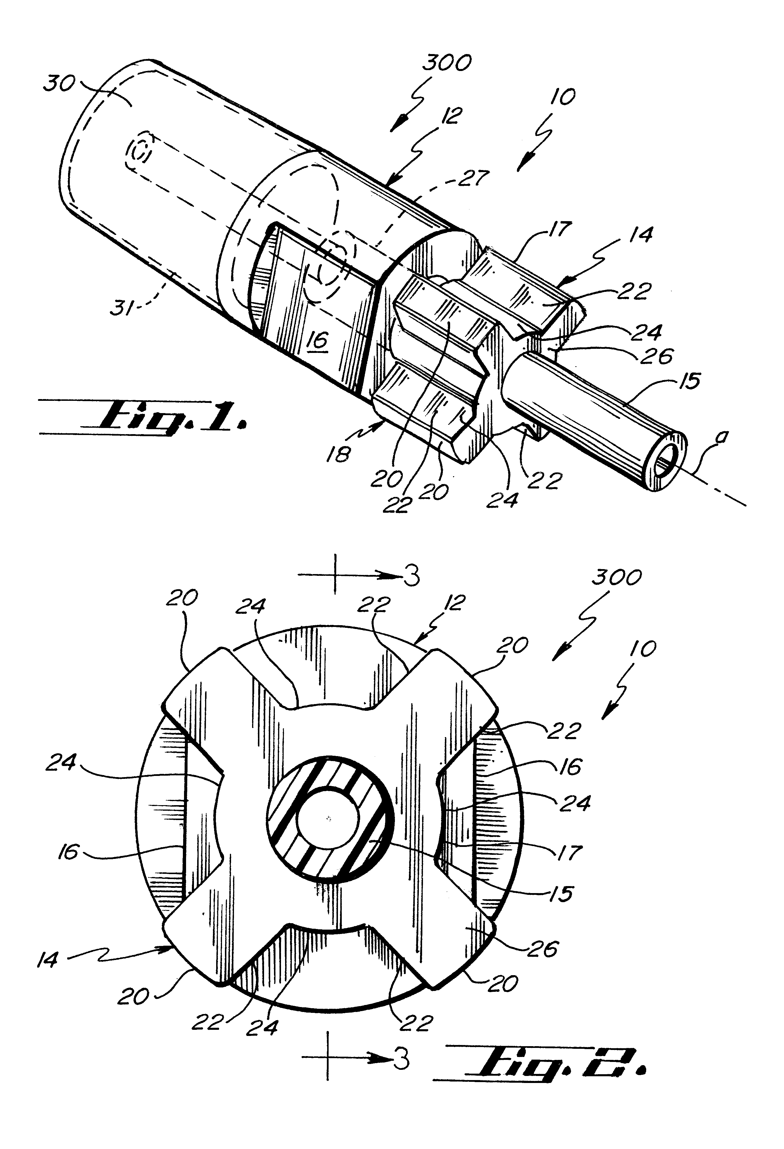
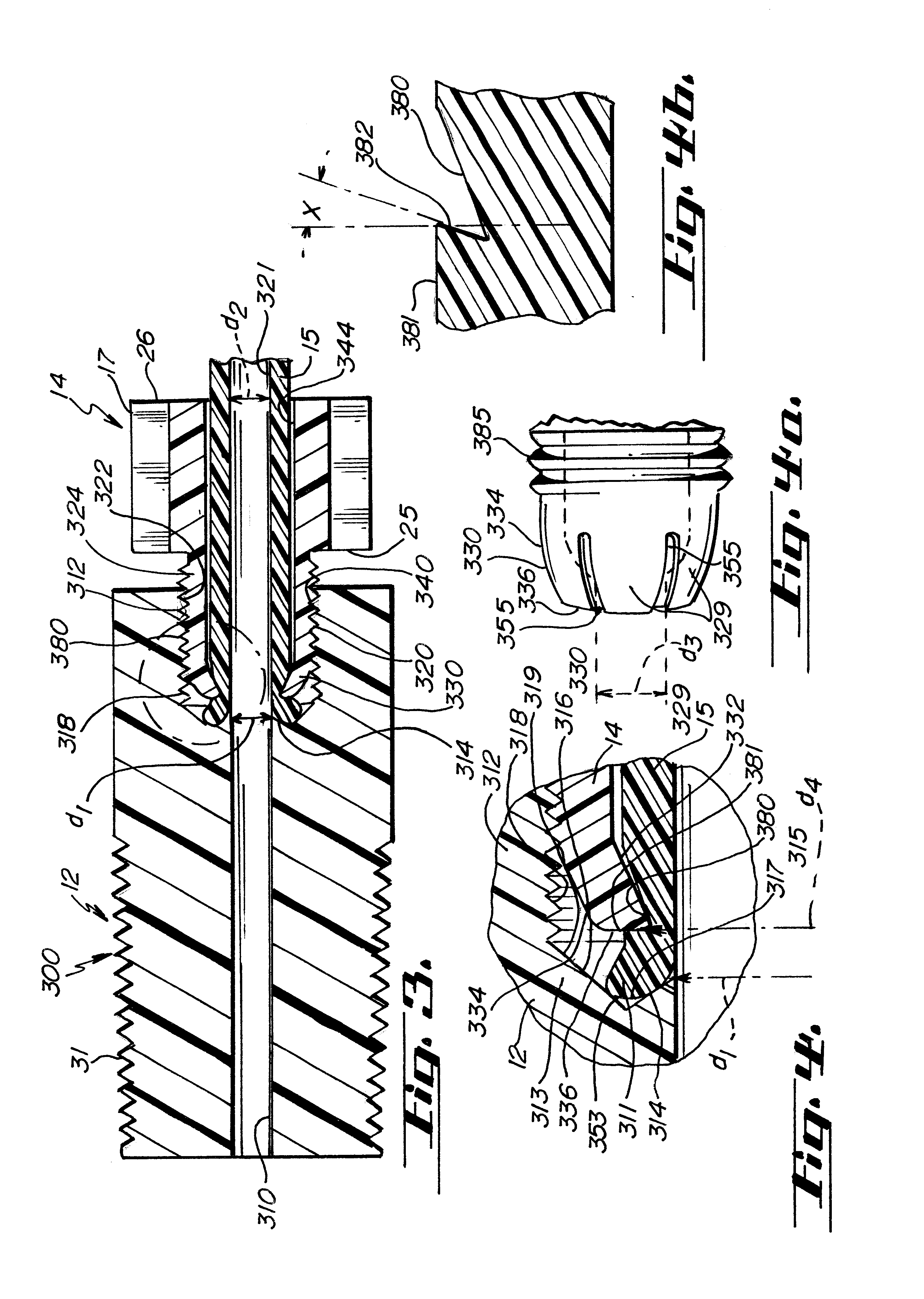
Referring to FIGS. 1-6, different embodiments of self-flaring fittings 10 are illustrated. Each generally comprises a fitting body 12 and a fitting nut 14 to provide a self flaring connection to a tubing section end portion 15. The tubing end portion, fitting nut, and fitting body are all coaxial about axis A.

Referring to FIGS. 1 and 2, a first embodiment 300 of a self-flaring ...


PUM

PropertyMeasurementUnit
outer diameteraaaaaaaaaa
inner diameteraaaaaaaaaa
diameteraaaaaaaaaa

Abstract

The self-flaring plastic fitting is generally utilized in coupling one section of tubing to another section of tubing. In the present invention, at least one of the sections of tubing has an end portion with a substantially uniform diameter and a groove about its periphery. The fitting itself includes a fitting body and a fitting nut. The fitting body is provided with a tapered nose section while the fitting nut is provided with a groove engaging device. In assembling the fitting, the end of the section of tubing incorporating the groove is place proximate the tapered nose section of the fitting body while the opposite end of the section of tubing is inserted through the fitting nut. The fitting nut is then pushed towards the fitting body where the groove engaging device of the fitting nut engages the groove of the tubing. As the fitting nut is joined with the fitting body, the fitting nut is drawn over the fitting body and, correspondingly, the tubing is drawn against and over the tapered nose section of the fitting body causing the tubing to flare and a seal to be created between the tapered nose section and tubing.

Description

FIELD OF THE INVENTIONThe present invention relates to plastic fittings for joining sections of plastic tubing, and, more particularly, to plastic flare fittings.BACKGROUND OF THE INVENTIONNumerous industries use metallic tubes and fittings of copper, stainless steel, steel and various metal alloys where connection of high strength and integrity are needed. Metallic plumbing is very suitable in many applications. However, in certain industries, the fluids conveyed may attack metal components and the metal can contaminate the conveyed fluids, i.e., the semiconductor processing industry. Highly inert fluoropolymers may be utilized for the fittings, tubing, and components in such applications, for example, polytetrafluoroethylene (PTFE), and perfluoroalkoloxy (PFA). To maintain a clean and non-hazardous environment, it is essential that the fittings provided for coupling to sections of tubing are not easily unintentionally disconnected and that the tubing / fitting sealing interface main...

Claims


Application Information

Patent Timeline
Patent Type & Authority Patents(United States)
IPC IPC(8): F16L19/00F16L47/00F16L47/04F16L19/065F16L19/02F16L19/028
CPCF16L19/0231F16L19/0283F16L19/0656F16L47/04
Inventor DONOHO, JAMESSTOICK, MICHAELSODERSTROM, ERIC
Owner FLUO ROWARE INC
Why Eureka
Try Eureka