Apparatus and method for facilitating accurate placement and installation of crown molding

Inactive Publication Date: 2002-07-09
LOCKLEAR THOMAS
View PDF20 Cites 12 Cited by
  • Summary
  • Abstract
  • Description
  • Claims
  • Application Information

AI Technical Summary

Benefits of technology

to provide an apparatus and method for facilitating

Problems solved by technology

However, because of the inherently elevated, overhead location of crown molding, installation can be cumbersome and difficult, sometimes requiring the cooperation of two or more workers.
This method frequently results in inaccurate molding placement as evidenced by the misalignment of intersecting crown molding segments at the corners of a room.
Misalignment of crown molding segments at the corner of a room is noticeable error that detracts from the aesthetically pleasing appearance of crown molding.
Such misalignm

Method used


Image

  • Apparatus and method for facilitating accurate placement and installation of crown molding
  • Apparatus and method for facilitating accurate placement and installation of crown molding
  • Apparatus and method for facilitating accurate placement and installation of crown molding

Examples


Embodiment Construction

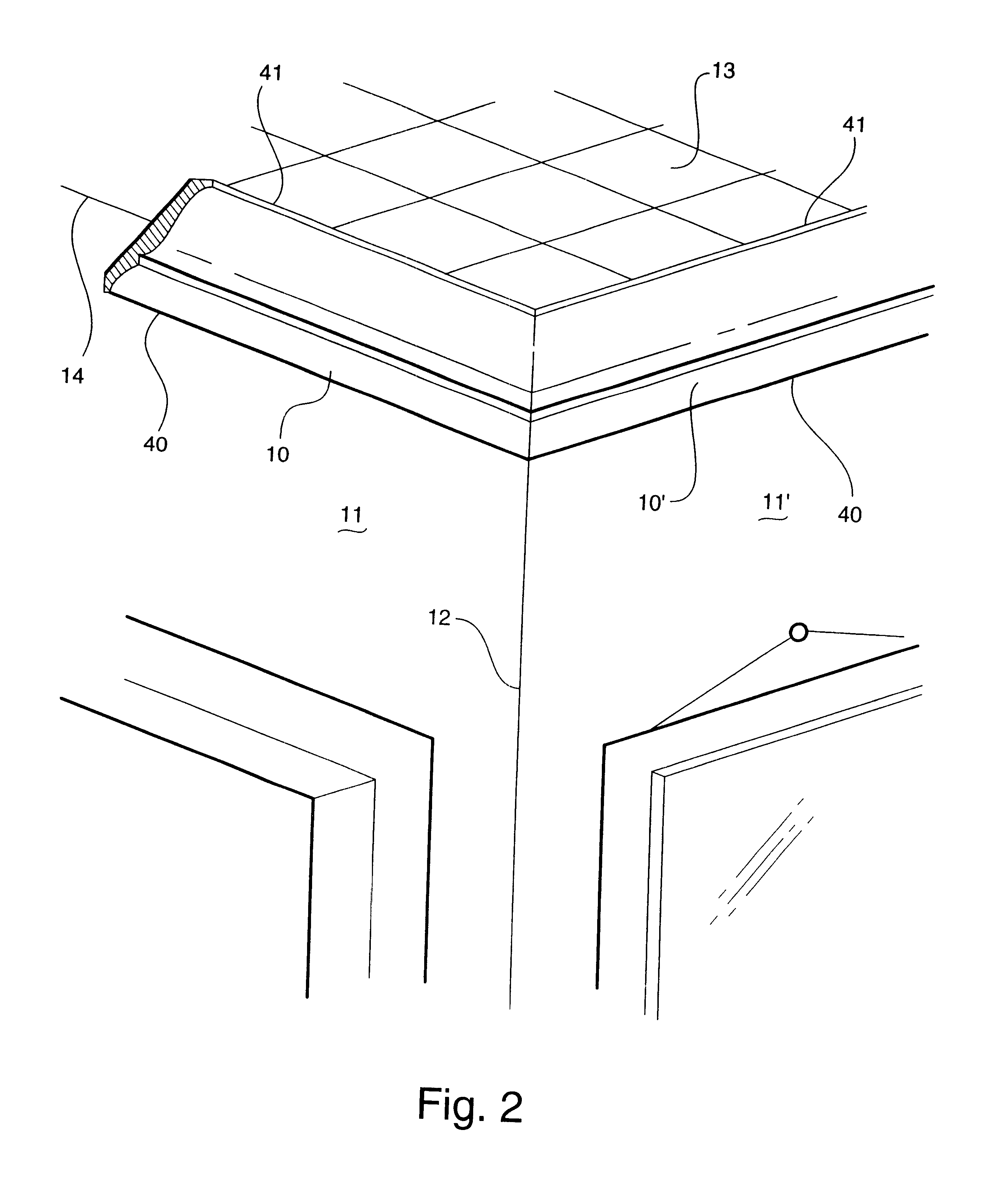
Referring now specifically to the drawings, segments of crown molding installed at a ceiling-to-wall intersection are shown broadly at reference numerals 10 and 10' in FIG. 2. Two walls 11 and 11' intersect to form a corner 12. The walls 11 and 11' also intersect with a ceiling 13. Properly aligned crown molding segments 10 and 10' are installed at the ceiling-to-wall intersection 14.

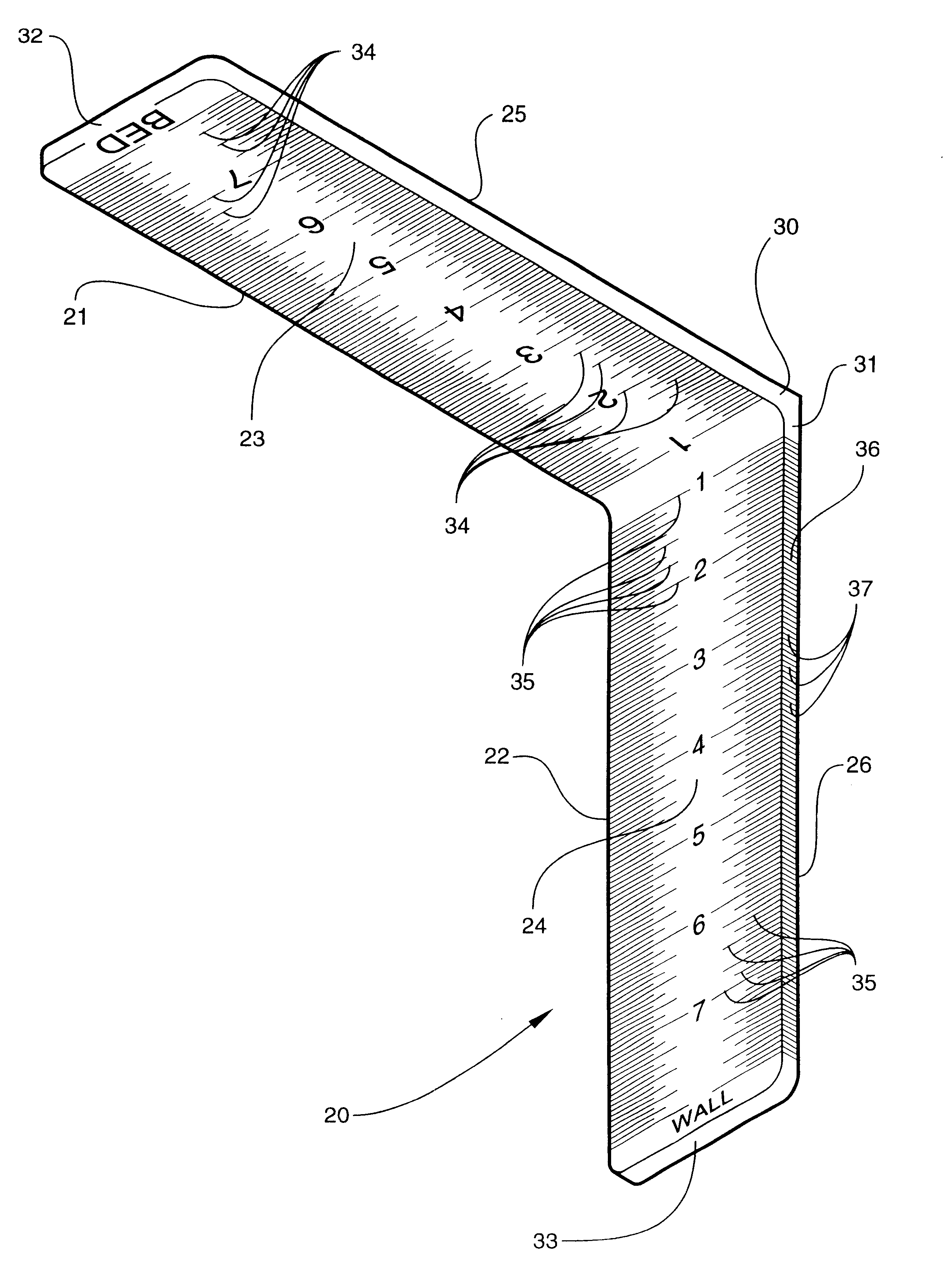
Turning now to FIG. 3, the tool is shown broadly at reference numeral 20. The tool 20 is comprised of a first extension arm 21 and a second extension arm 22. The extension arms 21 and 22 have respective inner major surfaces 23 and 24, outer major surfaces 25 and 26, proximal ends 30 and 31, and distal ends 32 and 33. The extension arms 21 and 22 are connected together at their proximal ends 30 and 31 such that their respective inner major surfaces 23 and 24 face other at right angles. The respective inner major surfaces 23 and 24 of the extension arms 21 and 22 are marked with respective measurement ind...


PUM


Abstract

A tool for facilitating accurate placement and installation of crown molding at an intersection of a ceiling and wall, the crown molding having a wall-engaging portion and a ceiling-engaging portion. The tool includes first and second extension arms, each extension arm having respective inner and outer major surfaces and respective proximal and distal ends. The first and second extension arms are connected together at their respective proximal ends such that their respective inner major surfaces face each other at right angles for receiving and orienting a sample section of the crown molding. The sample section includes a first longitudinal side edge representing the wall-engaging portion of the crown molding for residing adjacent the first extension arm and a opposing second longitudinal side edge representing the ceiling-engaging portion of the crown molding for residing adjacent the second extension arm. Measurement indicia are marked on each of the inner major surfaces of the first and second extension arms for measuring the sample section and determining the position of the crown molding at intersection of the ceiling and wall.

Description

TECHNICAL FIELD AND BACKGROUND OF INVENTIONThis invention relates to an apparatus and method for facilitating accurate placement and installation of crown molding.Crown molding serves several important aesthetic and utilitarian functions, including the obscuring of the rough and abrupt intersection of a ceiling and wall, the general enhancement and refinement of the decor and design of a room, and the stabilization of some wall coverings where they intersect with a ceiling. However, because of the inherently elevated, overhead location of crown molding, installation can be cumbersome and difficult, sometimes requiring the cooperation of two or more workers. Prior art methods of installing crown molding require the location of the molding to be determined by holding a segment of the molding against an intersecting ceiling and wall. This method frequently results in inaccurate molding placement as evidenced by the misalignment of intersecting crown molding segments at the corners of a...

Claims


Application Information

Patent Timeline
IPC IPC(8): B25H7/00E04F21/00E04F19/04
CPCB25H7/00E04F21/0007E04F21/003E04F19/0436E04F21/0069
Inventor LOCKLEAR, THOMAS
Owner LOCKLEAR THOMAS
Why Eureka
Try Eureka