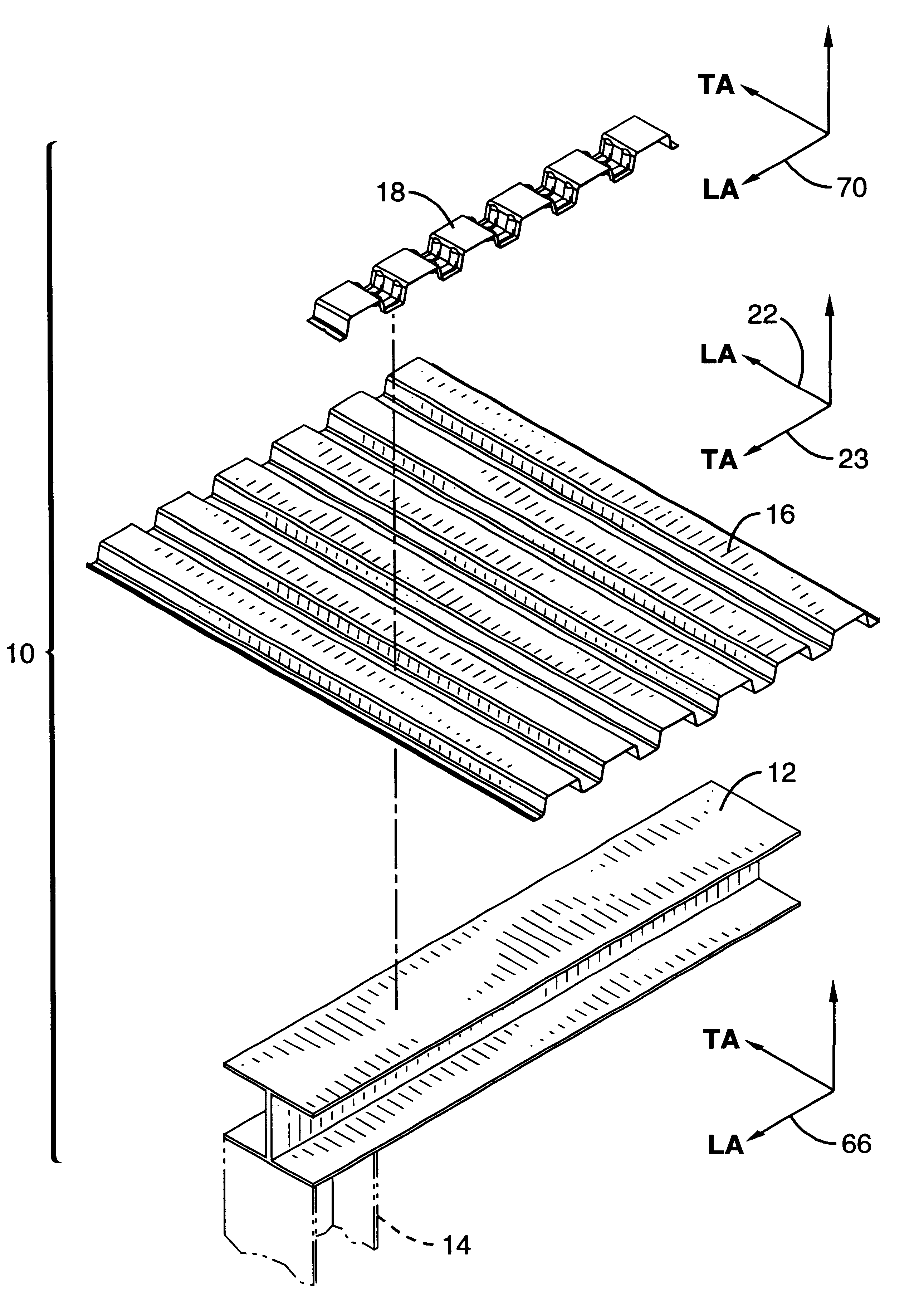
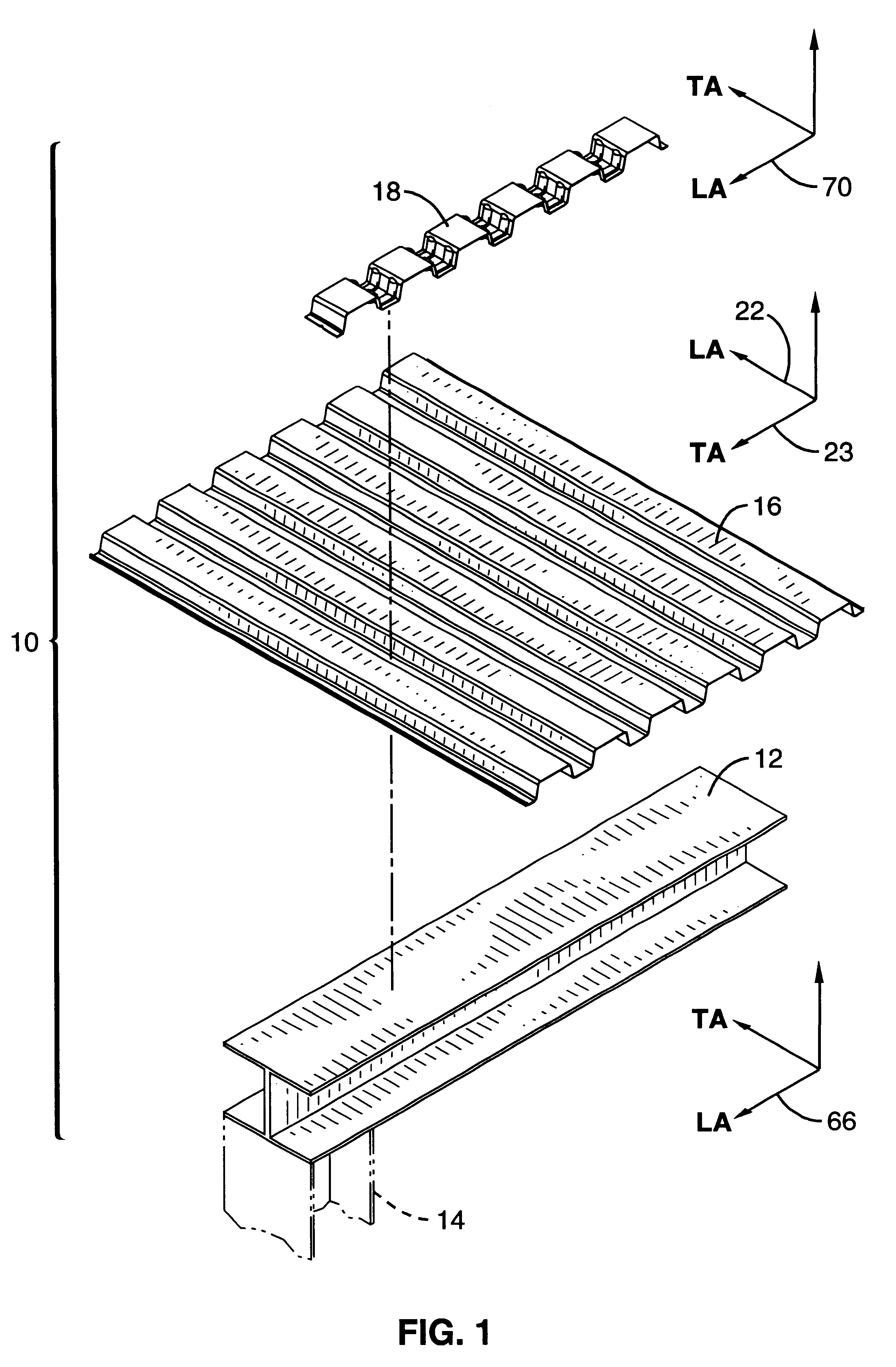
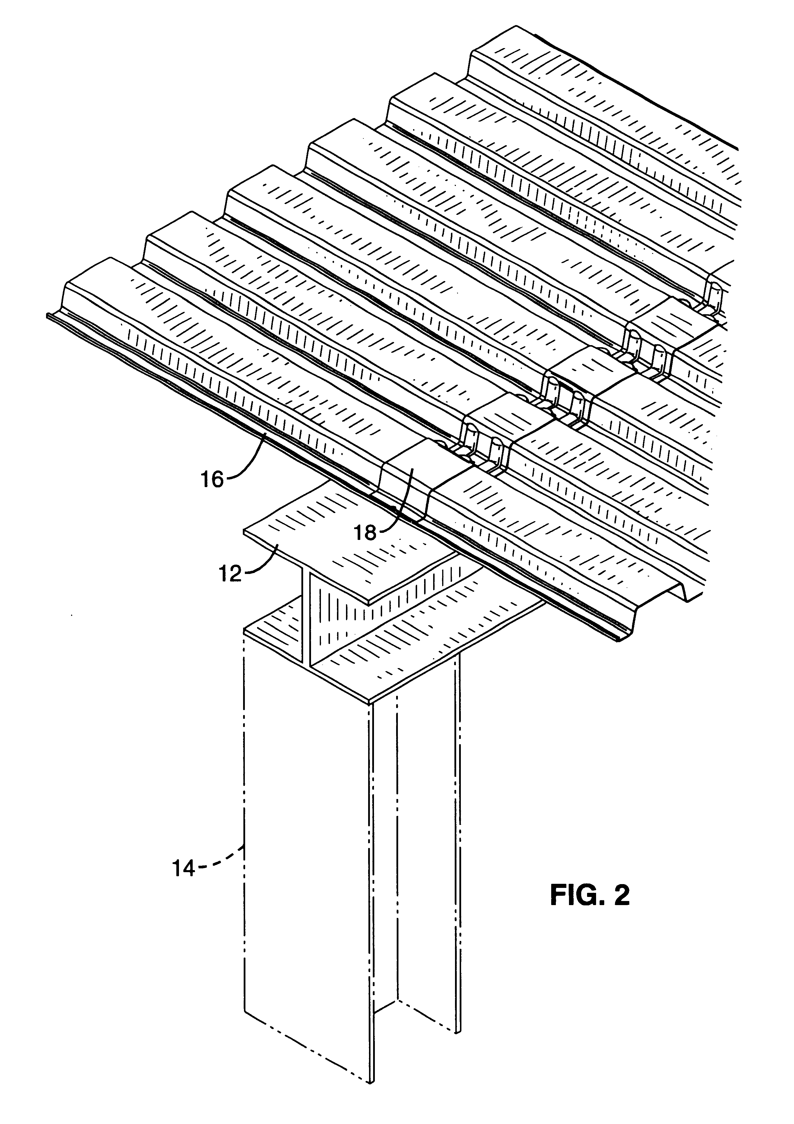
Corrugated stiffening member

a technology of stiffening member and profile plate, which is applied in the direction of manufacturing tools, building repairs, transportation and packaging, etc., can solve the problems of not easy to install and require considerable time and expense, the profile plate member does not provide shear resistance to both deck panels in the interior butt joint, and the diaphragm will eventually buckle or compress

Inactive Publication Date: 2002-07-09
DECK WEST
View PDF9 Cites 84 Cited by
  • Summary
  • Abstract
  • Description
  • Claims
  • Application Information

AI Technical Summary

Benefits of technology

to provide a stiffening member that

Problems solved by technology

If subjected to a horizontal shear force of sufficient strength, a diaphragm will eventually buckle or compress.
Although the profile plate member can be used where the deck abuts a vertical wall and on interior butt joints, it is not easy to install and requires considerable time and expense.
The profile plate member also does not provide shear resistance to both deck panels in an interior butt joint.
Thus, the known stiffening members

Method used


Image

  • Corrugated stiffening member
  • Corrugated stiffening member
  • Corrugated stiffening member

Examples


first embodiment

In stiffening member 18, as shown in FIGS. 11 and 12, a series of substantially identical pairs of first and second raised ribs 108 and 110 project from stiffening member 18's outer surface 84 along each U-shaped portion 72. Raised ribs 108 and 110 are parallel to each other and extend parallel to side edges 80 and 82, preferably continuously from third corner 96 down first side portion 86 to first corner 92, along floor portion 88 to second corner 94, and up second side portion 90 to fourth corner 98. In a stiffening member 18 that is three and one-half inches wide, the preferred dimensions are as follows. Each raised rib 108 and 110 is preferably about seven-eighths inch wide. Raised ribs 108 and 110 are preferably about one inch apart and equidistant from the longitudinal midline of U-shaped portion 72. Measured from the midpoint of its width, raised rib 108 is preferably located three-eighths inch from first side edge 80. Measured from the midpoint of its width, raised rib 110 i...

second embodiment

In the invention, as shown in FIG. 14, stiffening member 111 has a series of substantially identical pairs of planar tab portions 112 that project from stiffening member 111's outer surface 84 along each U-shaped portion 72. Each tab portion 112 is attached to first side portion 86, floor portion 88, and second side portion 90, at first side edge 80 or second side edge 82, perpendicular to the plane of the side portion or floor portion to which it is attached. Tab portions 112 extend, preferably continuously, from third corner 96 down first side portion 86 to first corner 92, along floor portion 88 to second corner 94, and up second side portion 90 to fourth corner 98. Thus, tab portions 112 are preferably U-shaped, corresponding in shape to the U of stiffening member 111's U-shaped portion 72. Tab portions 112 are preferably integrally adjoined to stiffening member 111 and may be formed by rolling or folding edge portions of stiffening member 111's U-shaped portion. Tab portions 11...


PUM


Abstract

A stiffening member, as well as a diaphragm of a building in which the stiffening member is used, is disclosed. The diaphragm includes a horizontal wide-flange beam, a corrugated deck, and a corrugated stiffening member. The stiffening member is an elongate, corrugated strip. The stiffening member's corrugations are formed by a series of U-shaped portions that alternate with, and are integrally connected to, a series of horizontal upper portions. Each U-shaped portion consists of three planar portions: two substantially vertical side portions and one horizontal floor portion. Each U-shaped portion is reinforced with two parallel raised ribs. In a second embodiment of the stiffening member, the U-shaped portion is reinforced with two parallel tab portions attached at the sides of the stiffening member. The stiffening member nestingly overlies the corrugated deck, and is attached to the deck and to the underlying horizontal beam with either welds or pins.

Description

1. Field of the InventionThe present invention relates generally to stiffening members used in constructing buildings to resist horizontal shear forces and, more particularly, to metal stiffening members used to reinforce roofs and floors of corrugated metal decking.2. Description of the Related ArtCorrugated metal decking is used in the construction of large buildings, as part of a horizontal floor or roof structure. Such structures are generally referred to as diaphragms. In addition to serving as floors and roofs, diaphragms give the building resistance to horizontal shear forces, such as are caused by wind and earthquakes.A corrugated deck consists of multiple deck panels. Each panel consists of repeating corrugations, where the corrugations extend parallel to the longitudinal axis of the deck panel. Deck panels are usually attached to each other at their side (longitudinal) edges by an overlapping joint known as a sidelap joint. Deck panels are also usually attached to each oth...

Claims


Application Information

Patent Timeline
IPC IPC(8): E04D3/38E04C2/32E04D3/00E04D3/366E04B5/32E04B5/40E04D3/24E04D3/36E04D3/30
CPCE04B5/40E04C2/322E04D3/30E04D3/366E04D3/38Y10T428/12347Y10T428/12417Y10T428/1241Y10T428/12382Y10T428/1234Y10S52/15
Inventor SHIPMAN, JERRYOEHRLEIN, WILLIEORGON, JOE
Owner DECK WEST
Why Eureka
Try Eureka