Superconducting cable for alternating current

a superconducting cable and alternating current technology, applied in the superconducting field, can solve the problems of deteriorating the critical current characteristic of the superconducting wire, increasing the loss of alternating current, and disturbance of winding

Inactive Publication Date: 2002-07-09
FURUKAWA ELECTRIC CO LTD
View PDF8 Cites 20 Cited by
  • Summary
  • Abstract
  • Description
  • Claims
  • Application Information

AI Technical Summary

Problems solved by technology

Furthermore, a recent study conducted by the present inventors has revealed that a circumferential magnetic field was considered a primary cause for magnetization loss, however, the longitudinal magnetization that remains within the tape increases alternating current loss (magnetization loss due to the longitudinal magnetization), which prevents the superconducting cable from having decreased alternating current loss.
As a result, bending distortion becomes large, thus deteriorating the critical current characteristic of a superconducting wire.
On the other hand, with the winding pitch being over 1000 mm, a winding force required to wind the tape around the center member is lowered, thus causing disturbances in winding.
More specifically, (1) when each layer of the conductor layers is wound in the same direction, the longitudinal magnetic field is large, so that eddy current is caused in the center member due to the longitudinal magnetic field, thus increasing the alternating current loss.
(2) When conductor layers and the shielding layers are wound, layers by layers, in alternate direction, with the same winding pitchs in order to decrease the alternating current loss of the superconducting cable due to its longitudinal magnetic field, current that should flow into each layer shifts to outer layers, resulting in that a current distribution over the layers becomes unbalanced, thereby leading to a large amount of alternating current loss.
On the other hand, when wires are wound in the same direction in spiral forms and the winding pitch becomes shorter as the winding advances to an outer one in order to obtain a uniform current distribution over the layers, alternating current loss occurs due to the longitudinal magnetic field, resulting in that expected alternating current loss cannot be attained.
This longitudinal magnetic field causes eddy current in the center member or the like, which leads to a large amount of alternating current loss.
As a result, the alternating current loss increases.

Method used


Image

  • Superconducting cable for alternating current
  • Superconducting cable for alternating current
  • Superconducting cable for alternating current

Examples


example 1

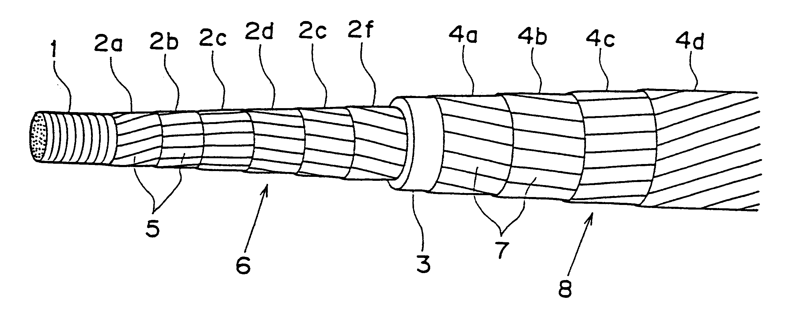
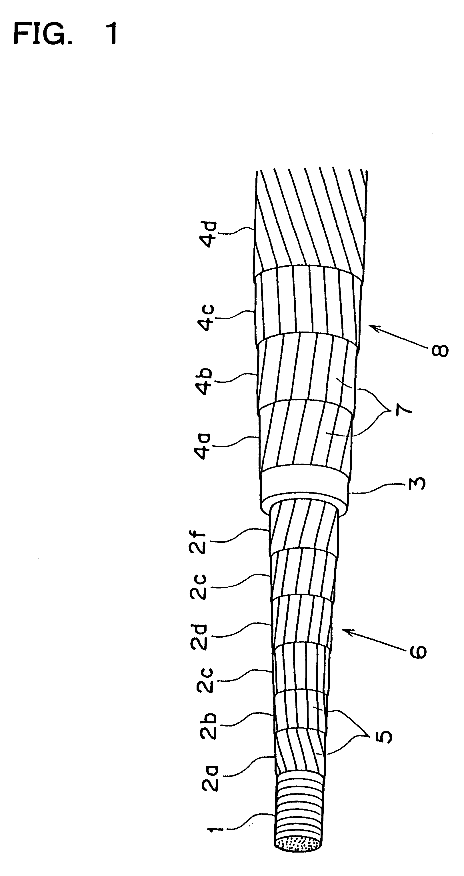
FIG. 1 shows a schematic side view for explaining a multi-layer superconducting cable in this example. A center member 1 is 18 mm in outer diameter and shaped into a flexible hollow pipe made of copper. On and around the center member 1, tape-shaped superconducting wires 5, which is 3 mm in width and 0.2 mm in thickness, were wound in spiral form to provide six layers from a layer 2a to a layer 2f, thereby forming conductor layers 6. On and around the conductor layers (superconducting layer) 6, a polypropylene laminated paper tape, which is 30 mm in width and 0.1 mm in thickness) was wound in a spiral form to have a plurality of layers laminated one after another. The tapes were laminated up to a thickness of 6 mm, thus forming an electrically insulating layer 3. On and around the electrically insulating layer 3, a tape-shaped superconducting wire 7 of which width is 3 mm (the same in width as the conductor layers) and of which thickness is 0.2 mm was wound in spiral form to form fo...

example 2

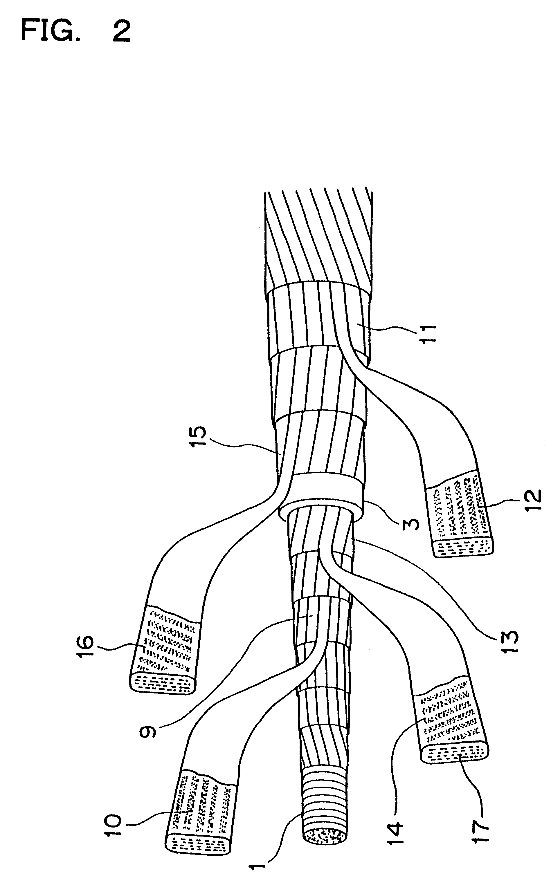
FIG. 2 shows another superconducting cable for alternating current according to the present invention. In the similar manners to those in Example 1, the conductor layers, insulating layers, and shielding layers were formed. In fabricating this superconducting cable, an intermediate conductor layer (the (N / 2+1)-th layer) 9 is wound using a tape-shaped superconducting wire 10 with untwisted filaments. In addition, an intermediate shielding layer (the (n / 2+1)-th layer) 11 is wound using a tape-shaped superconducting wire 13 with untwisted filaments. The outermost conductor layer (the N-th layer) 13 is formed using a tape-shaped superconducting wire 14 with twisted filaments 17. Furthermore, the innermost shielding layer (the first layer) 15 is formed using a tape-shaped superconducting wire 16 with twisted filaments.

Alternating current of 3000 A was supplied through the conductors. As a result, it is found that the alternating current loss further reduces by 1 / 2, compared to a cable in...

example 3

As an example 3, there will be explained a cable having conductor layers and shielding layers, in which the number of conductor layers and the number of shielding layers are odd, respectively. In the similar manners to those in Example 1, a center member is 18 mm in outer diameter and shaped into a flexible hollow pipe made of copper. On and around the center member, tape-shaped superconducting wires were wound in spiral form to provide seven layers, thereby forming conductor layers. On and around the conductor layers (superconducting layer), a polypropylene laminated paper tapes were wound in a spiral form to have a plurality of layers laminated one after another. The tapes were laminated up to a thickness of 6 mm, thus forming an electrically insulating layer. On and around the electrically insulating layer, like the conductor layers, a tape-shaped superconducting wires were wound in spiral form to form five layers, thereby providing shielding layers. The winding directions and wi...


PUM

PropertyMeasurementUnit
bend radiusaaaaaaaaaa
lengthaaaaaaaaaa
lengthaaaaaaaaaa

Abstract

A superconducting cable for alternating current, comprising conductor layers formed by a plurality of tape-shaped superconducting wires wound around a center member, an electric insulating layer formed outside the conductor layers, and a plurality of shielding layers formed outside the insulating layer, wherein, the conductor layers are formed, where N is a number of layers in the conductor layers and expressed by an integer, by gradually increasing a winding pitch of conductor layers in the same direction from an inner first layer to an N / 2 layer when the number of layers is even, or from an inner first layer to a (N-1) / 2 layer when the number of layers is odd, and then by gradually decreasing a winding pitch of conductor layers in an opposite direction to the inner layers from a N / 2+1 layer to an N layer when the number of layers is even, or from a (N+1) / 2 layer to an N layer when the number of layers is odd.

Description

The present invention relates to a superconducting power-transmission cable using superconductive materials, and in particular, to a superconducting power-transmission cable of which conductor layers and shielding layers are adjusted in both winding pitchs and winding directions.RELATED ARTIn superconducting cables for transmitting power with less loss, a conductor is formed by winding tape-shaped superconducting wires around a core or the like in spiral forms, so that flexibility is given to the cable itself. When the cable is required to transmit a large amount of current, the number of layers in the conductor is increased so as to form multi-layered conductor, thus increasing current capacity. Furthermore, in order that an electromagnetic field generated by current flowing through the conductor is avoided from leaking out of the cable, an insulator is formed on and around the outer surface of the conductor, and then tape-shaped superconducting wires are wound on and around the in...

Claims


Application Information

Patent Timeline
Patent Type & Authority Patents(United States)
IPC IPC(8): H01B12/02H01B12/06
CPCH01B12/02Y10T29/49014Y02E40/641Y02E40/60
Inventor MUKOYAMA, SHINICHITSUBOUCHI, HIROKAZUMIYOSHI, KAZUTOMI
Owner FURUKAWA ELECTRIC CO LTD
Why Eureka
Try Eureka