
Building component spacer brace

Inactive Publication Date: 2002-07-16
MITEK HLDG INC
View PDF49 Cites 85 Cited by
  • Summary
  • Abstract
  • Description
  • Claims
  • Application Information

AI Technical Summary

Benefits of technology

Yet another need exists for a spacer bar with the above-mentioned characteristics that does not have to be removed prior to installing roof or floor decking materials.
It is a feature of the present invention to provide a spacer bar for structural building components such as trusses and the like that is easy to manufacture and install.
It is another feature of the present invention to provide a spacer bar that will rigidly support trusses in position during installation of fasteners such as nails, screws and the like to further affix the spacer bar to the trusses.
Yet another feature of the present invention is to provide a spacer bar with the above-mentioned characteristics that does not have to be removed prior to installing roof or floor decking materials.
Yet another feature of the present invention is to provide a means for supporting trusses or other building components on edge prior to fastening such components together. Thus, the present invention results in improved safety, because the installer is able to obtain the requisite tools and fasteners without having to simultaneously support the truss or building component in a desired orientation.
Accordingly, the present invention provides solutions to the shortcomings of prior truss spacer devices and braces. The subject invention is easy to manufacture and install. The subject invention may be installed on a plurality of trusses without risk of the trusses toppling as additional fasteners are installed. Those of ordinary skill in the art will readily appreciate, however, that these and other details, features and advantages will become further apparent as the following detailed description of the embodiments proceeds.

Problems solved by technology

Thus, prior to attaching the sheathing materials, a truss that is supported only at its bottom by its attachment to supporting walls can be prone to topple over on its side.
Such toppling over of even one truss can result in all of the trusses falling over similar to a row of dominos which can cause injury to construction personnel and damage the trusses and other building components.
However, many of such devices require that the bracing element be fastened to the respective truss member by a separate fastener before any lateral supporting of the truss is achieved.
Still others, while providing a modicum of lateral support to the trusses prior to affixing the brace devices to the trusses with mechanical fasteners (screws, nails, etc.), are difficult to manufacture.
Other such devices fail to provide adequate support between adjacent truss members and are not suited for attachment to a variety of different truss materials.
Still some other devices employ teeth that must be hammered into the truss and, if not installed properly, can lead to splintering and truss damage.
Furthermore, such toothed devices will not work with steel trusses and other building components fabricated from steel.

Method used


Image

  • Building component spacer brace
  • Building component spacer brace
  • Building component spacer brace

Examples


Embodiment Construction

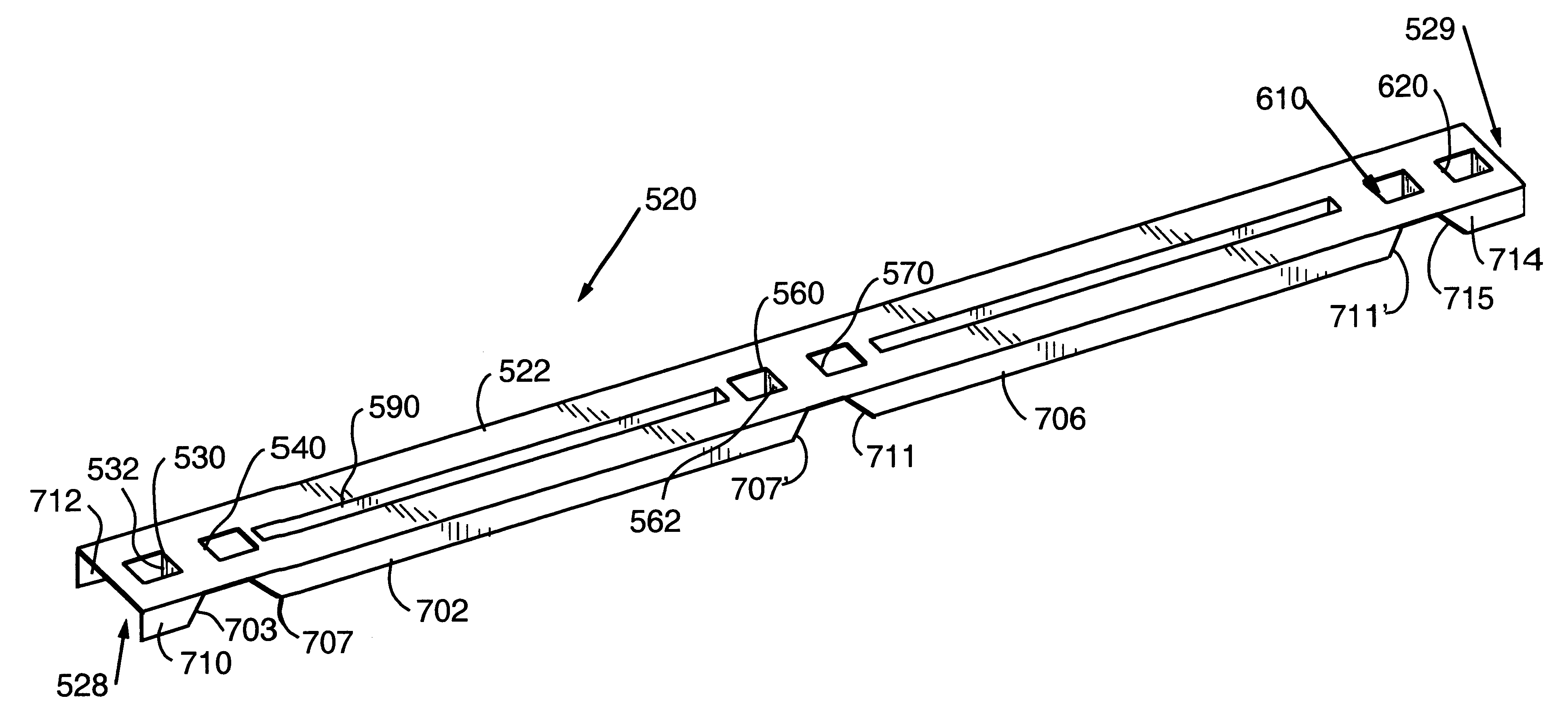
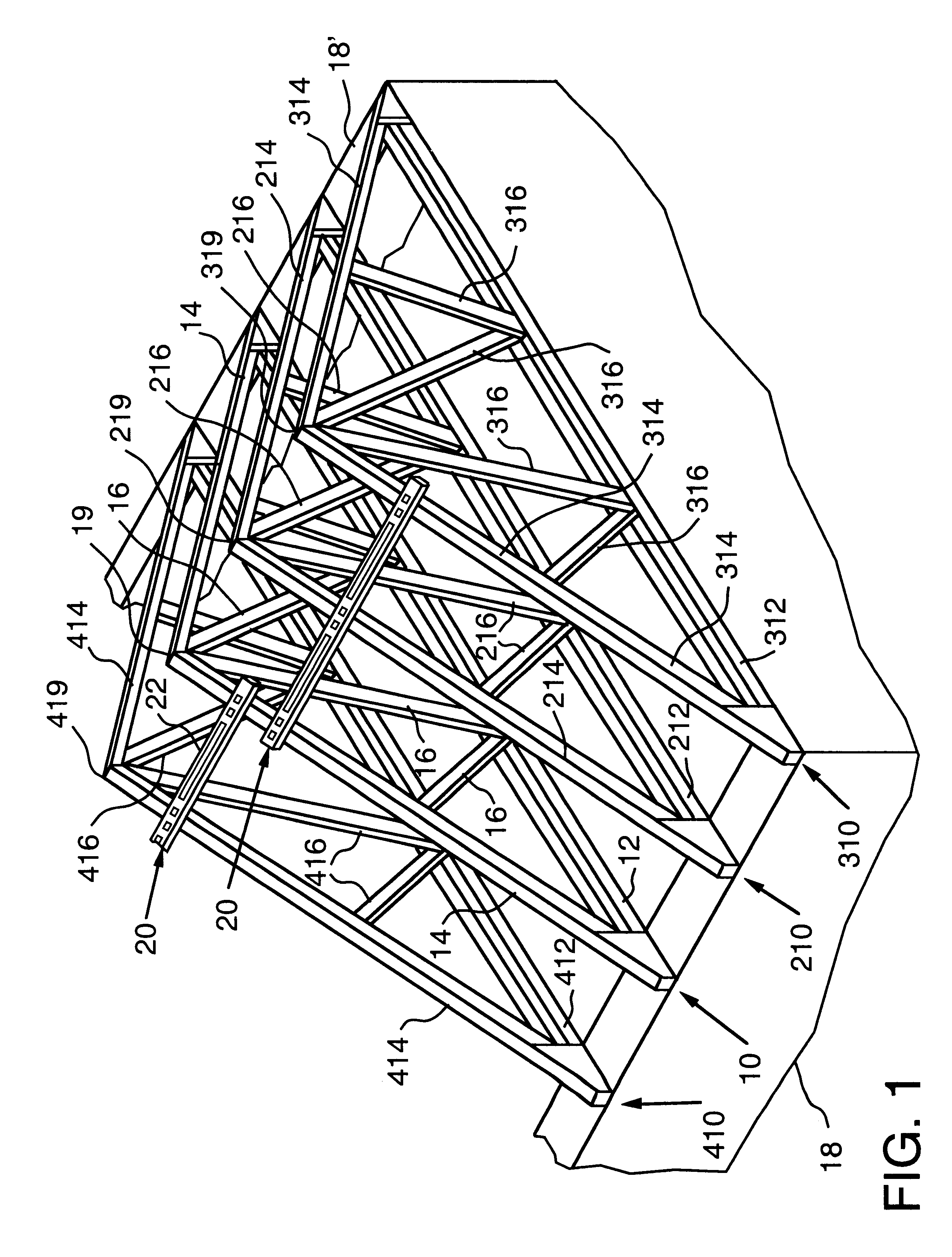
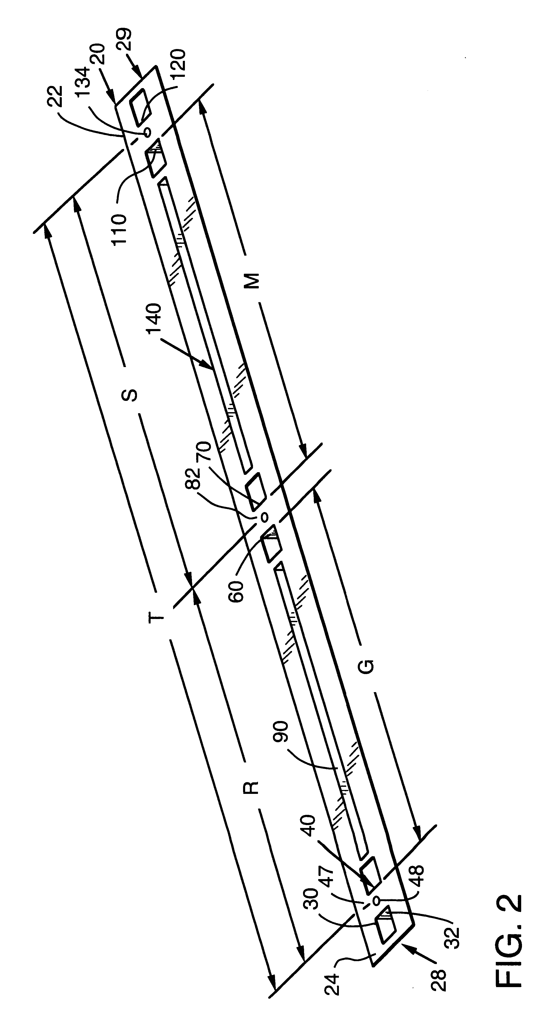
Referring now to the drawings for the purposes of illustrating the present embodiments of the invention only and not for the purposes of limiting the same, there is shown a spacer bar 20 of the present invention for use in connection with structural building components such as roof trusses, floor trusses, etc. FIG. 1 depicts two spacer bars of the present invention used in connection with a plurality of conventional roof trusses (10, 210, 310, 410). The reader will appreciate that truss 10 may comprise a bottom chord 12 and a pair of upper chords 14 that are attached at one of their respective ends to the bottom chord 12 at a desired pitch. The other ends of the upper chords 14 are attached together to form the peak 19. A plurality of appropriate web braces 16 are attached between the bottom chord 12 and the upper chords 14. Similarly, truss 210 includes a bottom chord 212, upper chords 214, web braces 216 and a peak 219. Truss 310 includes a bottom chord 312, upper chords 314, web ...


PUM


Abstract

A spacer bar for use in connection with support building components at predetermined intervals relative to each other. The spacer bar may be used in connection with building components fabricated from wood, metal, etc. and includes at least two pair of clamping tabs for engaging and retaining the components in the desired position.

Description

Not applicable.FEDERALLY SPONSORED RESEARCHNot applicable.1. Field of the InventionThe subject invention relates to devices for installing and supporting building components and, more particularly, to a spacer and support apparatus for supporting roof and floor trusses.2. Description of the Invention BackgroundA truss is a rigid framework of wooden or metal beams designed to support a structure, such as a roof. Trusses may also be employed to span between opposing support walls to create a floor supporting structure within a building. A truss system for supporting a floor may comprise a collection of trusses that are arranged adjacent to each other and span the distance between two or more support walls. Local building codes and structural design requirements generally govern the amount of spacing permitted between each truss. When anchored to the support walls, the tops of the trusses are substantially co-planar with each other to enable floor or roof decking materials to be attach...

Claims


Application Information

Patent Timeline
IPC IPC(8): E04G21/18E04B7/02E04C3/02
CPCE04B7/022E04C3/02E04G21/1891E04C2003/026
Inventor DAUDET, LARRY R.PONKO, EDMUND L.RALPH, GREGORY S.
Owner MITEK HLDG INC
Learn More