System for implementing a register free-list by using swap bit to select first or second register tag in retire queue

a register and free-list technology, applied in the field of microprocessors, can solve the problems of limiting the number of instructions that can be in flight, limiting the number of instructions in flight, and restoring physical registers to a non-speculative state,

Inactive Publication Date: 2002-07-23
ADVANCED MICRO DEVICES INC
View PDF6 Cites 28 Cited by
  • Summary
  • Abstract
  • Description
  • Claims
  • Application Information

AI Technical Summary

Problems solved by technology

Consequently, the limited number of architectural registers, can limit the number of instructions that can be in flight in a microprocessor since most instructions will require at least one physical register for a destination register.
The number of architectu

Method used


Image

  • System for implementing a register free-list by using swap bit to select first or second register tag in retire queue
  • System for implementing a register free-list by using swap bit to select first or second register tag in retire queue
  • System for implementing a register free-list by using swap bit to select first or second register tag in retire queue

Examples


first embodiment

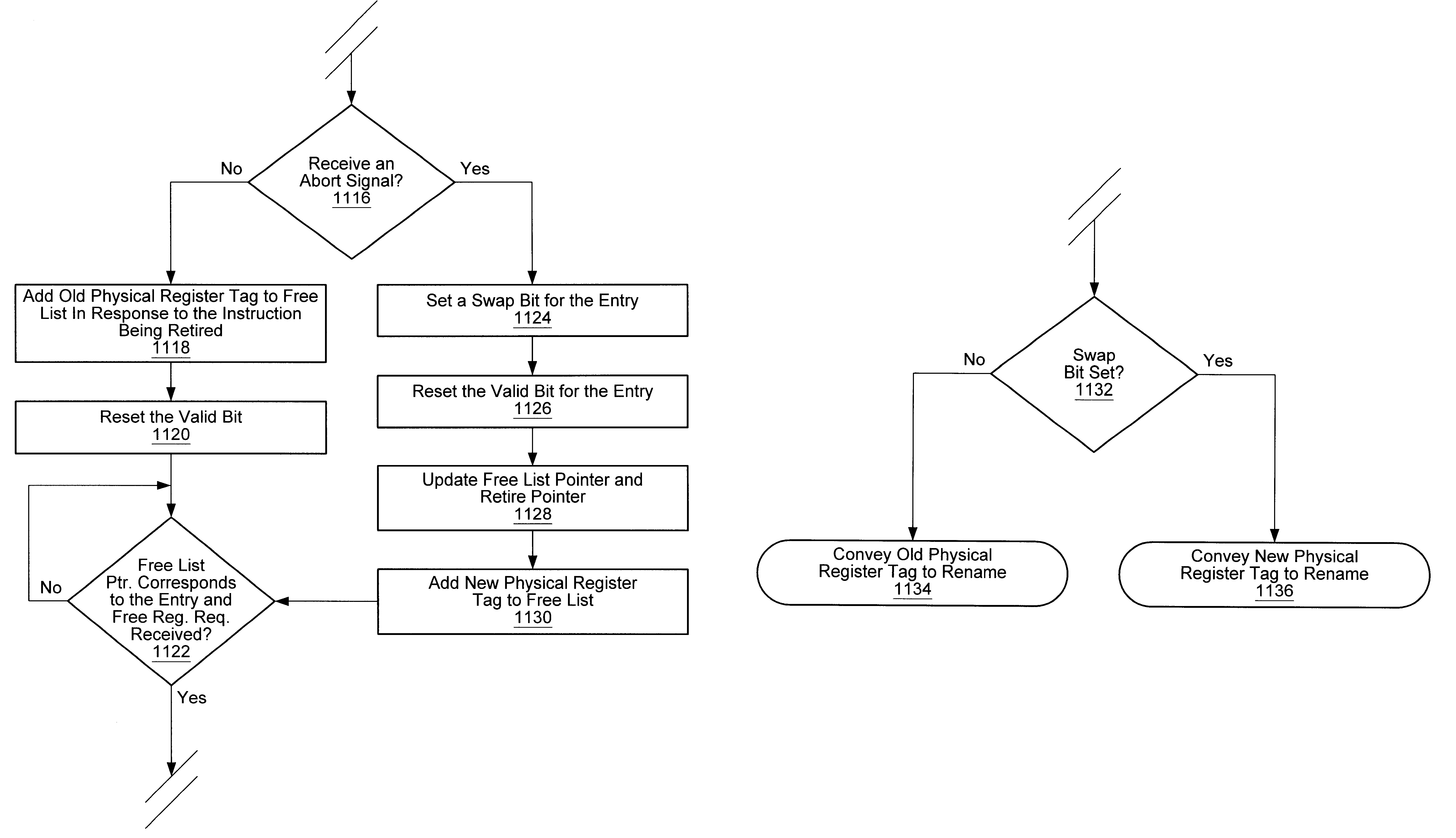
Turning to FIG. 4B, a block diagram of one portion of the retire queue of FIG. 4A is shown. Other embodiments are possible and contemplated. FIG. 4B includes a logical AND gate 940. As shown, logical AND gate 940 is coupled to receive a valid signal and an abort signal and is coupled to output a swap signal.

FIG. 4B depicts a first embodiment of a circuit configured to set swap bit 912 in response to an abort signal. Logical AND gate 940 can receive the value of valid bit 910 for an entry in retire queue 316. In response to receiving an abort signal, the output value (swap signal) of logical AND gate 940 can be stored in swap bit 912 for the entry corresponding to the valid bit 910.

second embodiment

Turning to FIG. 4C, a block diagram of one portion of the retire queue of FIG. 4A is shown. Other embodiments are possible and contemplated. FIG. 4C includes a buffer 960. As shown, buffer 960 is coupled to receive a valid signal and an abort signal and to output a swap signal.

FIG. 4C depicts a second embodiment of a circuit configured to set swap bit 912 in response to an abort signal. Buffer 960 can receive the value of valid bit 910 for an entry in retire queue 316. In response to receiving an abort signal, buffer 960 can convey the value of valid bit 910 as a swap signal. The swap signal can be stored in swap bit 912 for the entry corresponding to the valid bit 910.

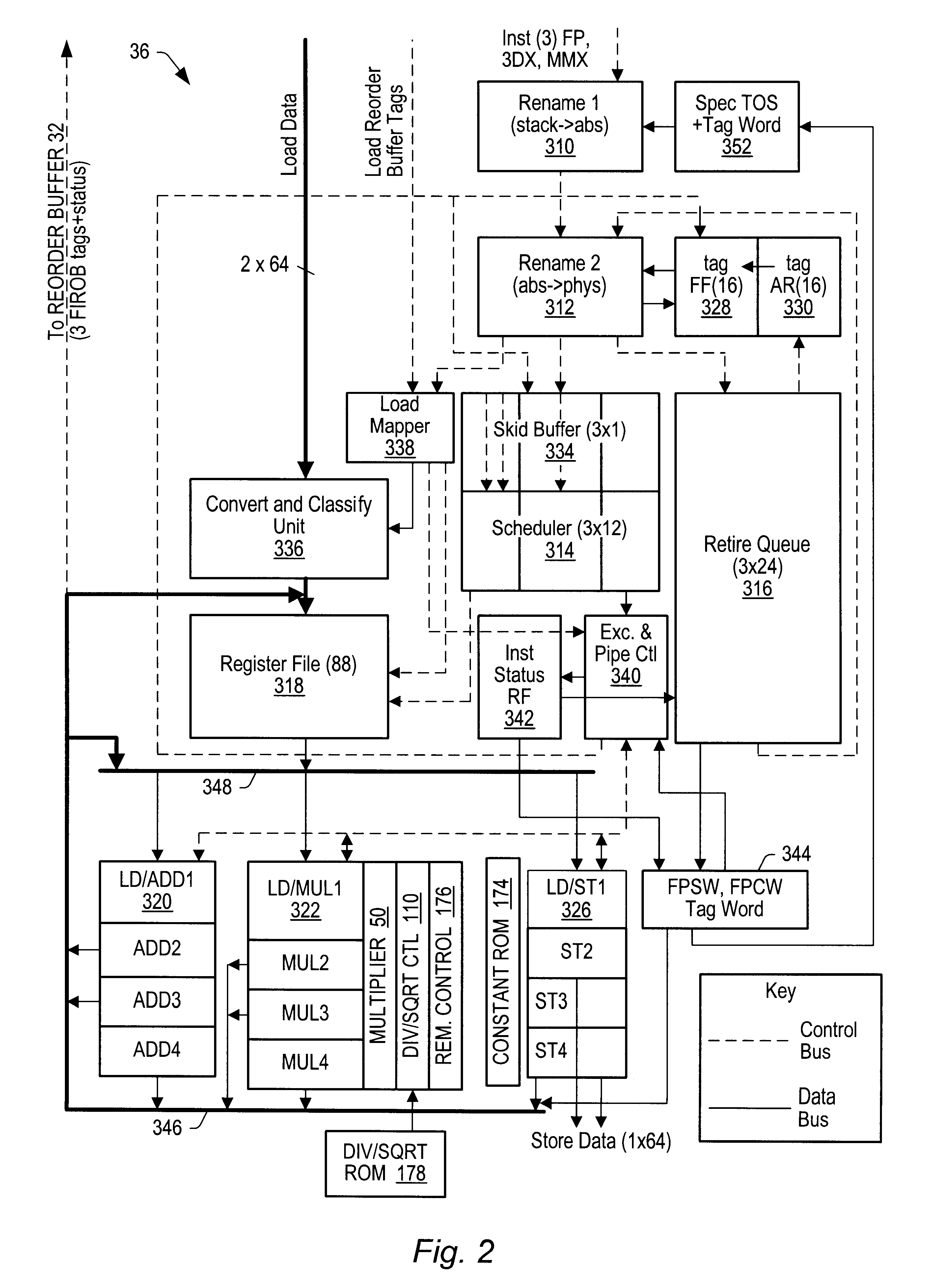
Turning to FIG. 5, a block diagram depicting portions of the floating-point unit of FIG. 2 is shown. FIG. 5 depicts rename 1 unit 310, rename 2 unit 312, retire queue 316, architectural register tag file 328, tag future file 330, and multiplexer (mux) 802. Rename 2 unit 312 includes future file update 804. Rename 1 un...


PUM


Abstract

An apparatus and method for implementing a register free list scheme is provided. An instruction received in an execution unit can be assigned an absolute register number as its destination register. A new physical register tag from a free list can be assigned to the absolute register number and a tag future file can be updated with the new physical register tag. The old physical register tag can be read from the tag future file and stored in a retire queue entry corresponding to the instruction along with the new physical register tag and an architectural register identifier corresponding to the absolute register number. A valid bit corresponding to the entry can be set in response to the entry being written. In response to an abort signal, a swap bit corresponding to the entry can be set, the valid bit can be reset, and the new physical register tag can be conveyed to a rename unit in response to receiving a free register request. In response to the entry being retired prior to receiving an abort signal, the valid bit corresponding to the entry can be reset and the old physical register tag can be conveyed to a rename unit in response to receiving a free register request.

Description

1. Field of the InventionThis invention relates generally to the field of microprocessors and, more particularly, to execution units within microprocessors.2. Description of the Related ArtMicroprocessors are typically designed to include a limited number of architectural registers. Architectural registers are often used by instructions to store intermediate and final results prior to storing the results to a cache or a main memory. Instructions often write results to at least one destination register. Consequently, the limited number of architectural registers, can limit the number of instructions that can be in flight in a microprocessor since most instructions will require at least one physical register for a destination register. The number of architectural registers can further limit the number of instructions in flight when register dependencies arise. Dependencies can arise when two or more instructions attempt to access or update the same register.A register renaming scheme ...

Claims


Application Information

Patent Timeline
IPC IPC(8): G06F9/38
CPCG06F9/3836G06F9/384G06F9/3859G06F9/3855G06F9/3857G06F9/3858G06F9/3856G06F9/38585
Inventor MEIER, STEPHANKELTCHER, CHETANA N.
Owner ADVANCED MICRO DEVICES INC
Why Eureka
Try Eureka