
Aerosol inhaler device

an aerosol and inhaler technology, which is applied in the direction of inhalators, medical atomisers, respirators, etc., can solve the problems of not providing the possibility of proper inhalation through the mouth, difficulty in providing sufficient air flow, and air passage next to the container itself, so as to reduce the pressure drop through the inspiratory part, the effect of reducing the resistance to air flow and avoiding turbulen

Inactive Publication Date: 2002-08-06
DRACHMANN BO +1
View PDF10 Cites 18 Cited by
  • Summary
  • Abstract
  • Description
  • Claims
  • Application Information

AI Technical Summary

Benefits of technology

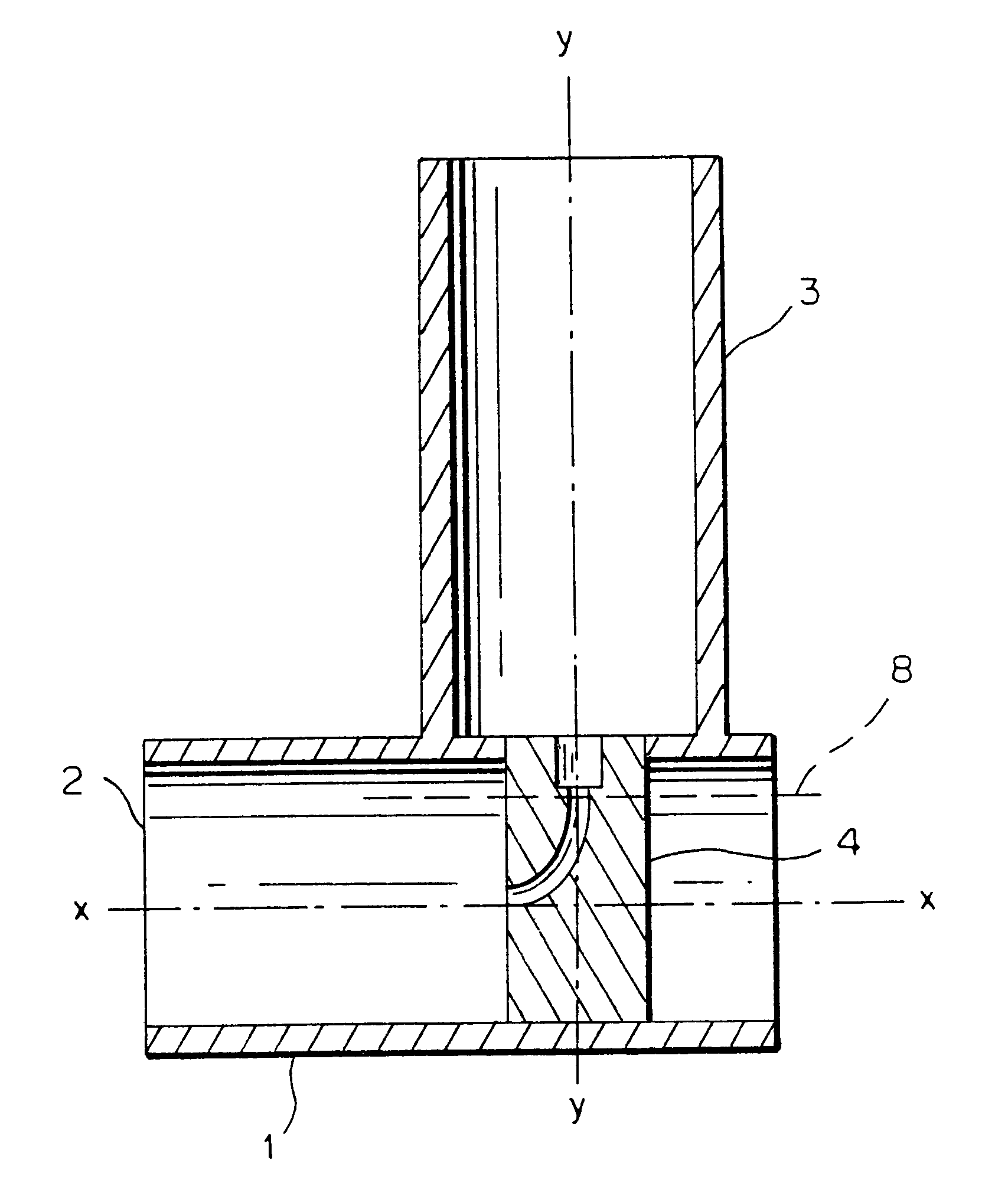
In a preferred embodiment the area of the flow. cross section in the inspiratory part, possibly apart from the area around the member for passage of aerosol, is substantially constant. This contributes to keeping down the pressure drop through the inspiratory part.
In a further preferred embodiment the member for passage of aerosol is at its exterior side aerodynamically designed such that it offers the least possible resistance to the air flow in the inspiratory part and creates the least possible turbulence.

Problems solved by technology

Common to these aerosol inhalation devices is, however, that air cannot flow freely through the device past the member for passage of aerosol and out through the mouthpiece, the flow path towards the member for passage of aerosol being partly blocked by the aerosol container.
This is a problem, as for instance asthmatics, which constitute a big group of users of aerosol inhalation devices, have difficulty in providing sufficient air flow for bringing the active particles of the aerosol down into the lungs.
1 / 3 or less of the active particles is deposited in the lungs, whereas the rest is deposited in the mouth and the throat, where it is undesirable from a medical point of view.
The air passage next to the container itself is, as mentioned, limited and does not provide the possibility of a proper inhalation through the mouth.
Through good coordination and technique about one third or less of the active particles is deposited in the lungs by this method, and the rest is deposited at the back of the throat, where it is not desirable from a medical point of view.
A comparatively huge intake of breath is required to catch the suspended particles and to take them to the lungs, and in that respect asthmatics are often not able to produce such an intake of breath or account of the asthma.
The depositing of the active particles of the aerosol in undesired places may besides have some side effects in the form of local irritations or may for instance result in fungus.
Therefore, patients are told to rinse the mouth after use of the aerosol, a request which however, is often not complied with.
These pressure drops, however, undesirable for the above reasons.
Such a baffle plate is, however, unreliable and thus unsuitable for conducting the aerosol in the desired direction.

Method used


Image

  • Aerosol inhaler device
  • Aerosol inhaler device
  • Aerosol inhaler device

Examples


Embodiment Construction

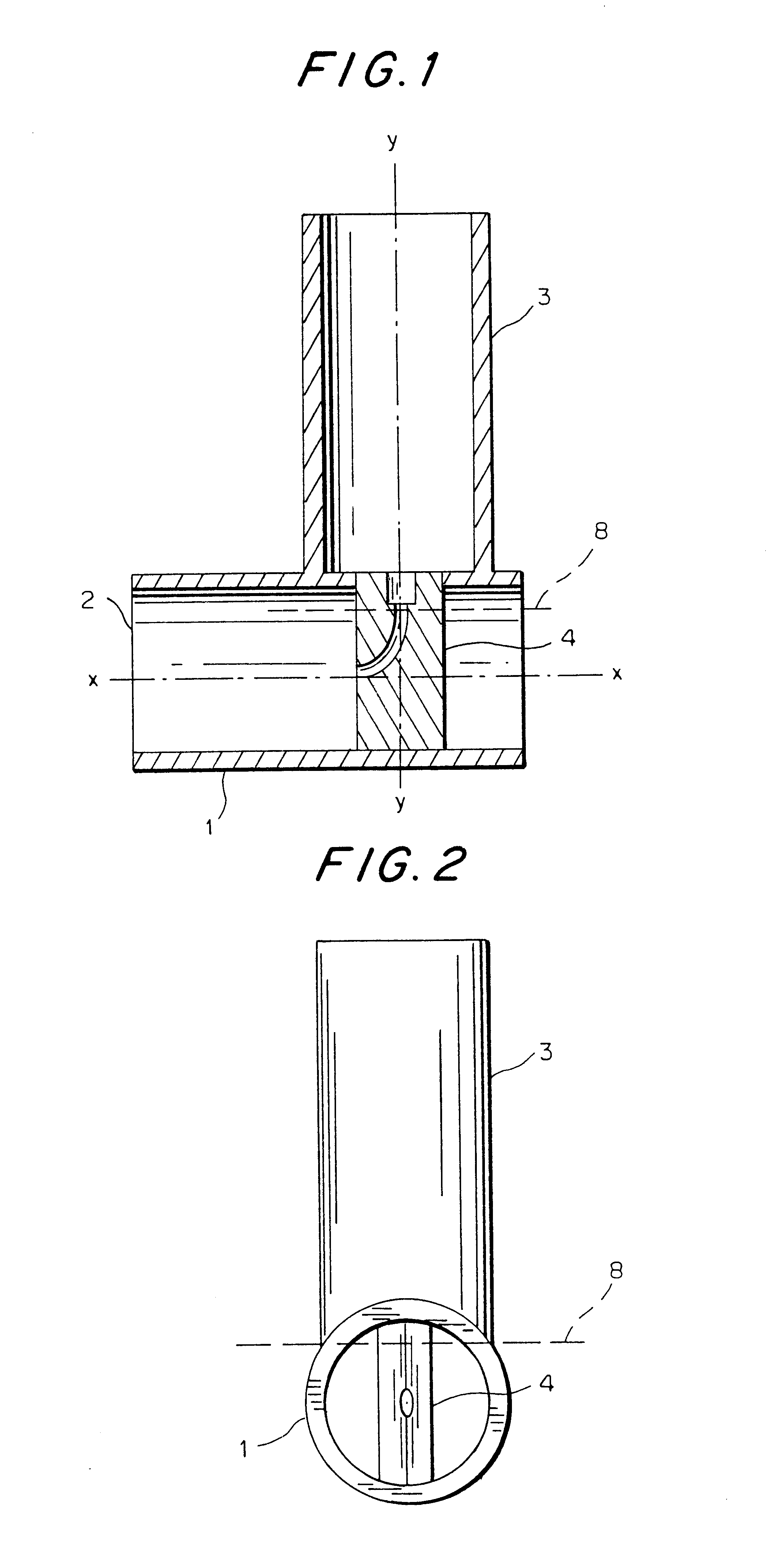
The inhalation device comprises an inspiratory part 1, which in the present example of an embodiment is constituted of a circular cylindrical tube open at both ends. One end of the tube constitutes a mouthpiece 2. Between its ends the inspiratory part 1 carries a holding part 3 for an aerosol container.

The aerosol container which is not shown is of the conventional type with a dispensing valve with an outlet tip in the form of a small tube.

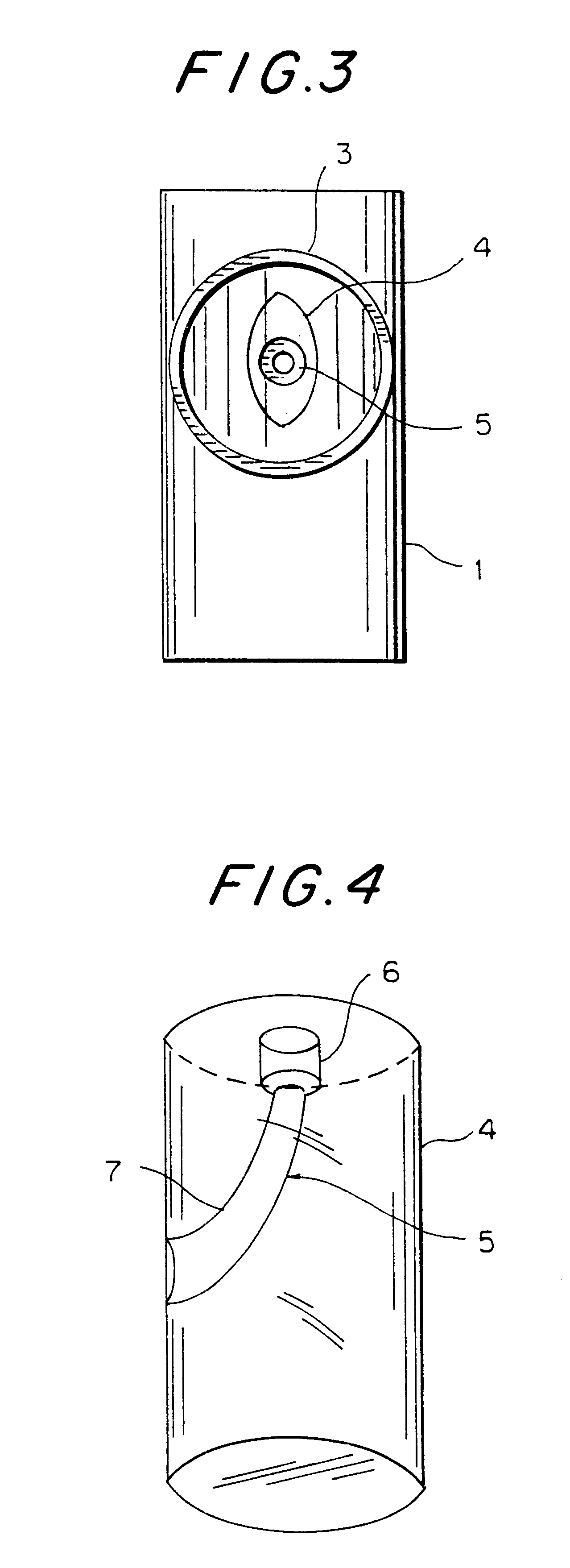
In the inspiratory part 1 a member 4 for passage of aerosol is provided, said member being shown in detail in FIG. 4. The member 4 for passage of aerosol consists in the embodiment shown in a cylindric, aerodynamically designed body extending transversely through the inspiratory part 1 and having the elliptical cross section shown in FIG. 3 in a plane 8 parallel to the central longitudinal axis x--x of inspiratory part 1 and perpendicular to the central axis y--y of the holding part 3. The member 4 for passage of aerosol has a conduit 5 with a fir...


PUM


Abstract

The aerosol inhalation device is manually operated and comprises a holding part (3) for receiving an aerosol container with a valve and an outlet tip, and an inspiratory part (1), which at one end comprises a mouthpiece (2), in which inspiratory part (1) a member (4) for passage of aerosol is provided for receiving the outlet end of the aerosol container and comprising a conduit (5) with an outlet opening for discharging aerosol into the inspiratory part in the direction towards the mouthpiece (2). At the end opposite the mouthpiece (2) the inspiratory part (1) is open towards the surroundings such that air may pass freely from the surroundings past the member (4) for passage of aerosol and out through the mouthpiece (2).

Description

The present application is the national stage under 35 U.S.C. 371 of PCT / EP98 / 00021, filed Jan. 16, 1998.1. Technical Field of the InventionThe present invention relates to a manually operated aerosol inhalation device comprising a holding part for receiving an aerosol container with a valve and an outlet tip, and an inspiratory part, which at one end comprises a mouthpiece, in which inspiratory part a member for passage of aerosol is provided for receiving the outlet tip of the aerosol container and comprising a conduit with an outlet opening for discharging charging aerosol into the inspiratory part in the direction towards the mouthpiece. Such inhalation devices are for instance known from DK-B-146675, DK-B-164082, DK-B-169464 and DK-B-169863.2. Prior ArtDK-B-146675 describes an aerosol inhalation device with a swingably openable lid which in its closed position covers an inserted aerosol container to prevent activation thereof and which covers the mouthpiece to prevent it from b...

Claims


Application Information

Patent Timeline
Patent Type & Authority Patents(United States)
IPC IPC(8): A61M15/00
CPCA61M15/009
Inventor DRACHMANN, BOANDERSEN, PER
Owner DRACHMANN BO
Learn More