
Torque sensor for a motor vehicle power train

a technology for torque sensors and motor vehicles, applied in the direction of belts/chains/gearrings, belt control, instruments, etc., can solve the problems of unfavorable use of power trains

Inactive Publication Date: 2002-08-13
LUK GETRIEBE SYST
View PDF6 Cites 5 Cited by
  • Summary
  • Abstract
  • Description
  • Claims
  • Application Information

AI Technical Summary

Benefits of technology

Another object of the invention is to provide a relatively simple, inexpensive, compact and highly versatile torque sensor for use in conjunction with a transmission in the power train of a motor vehicle.
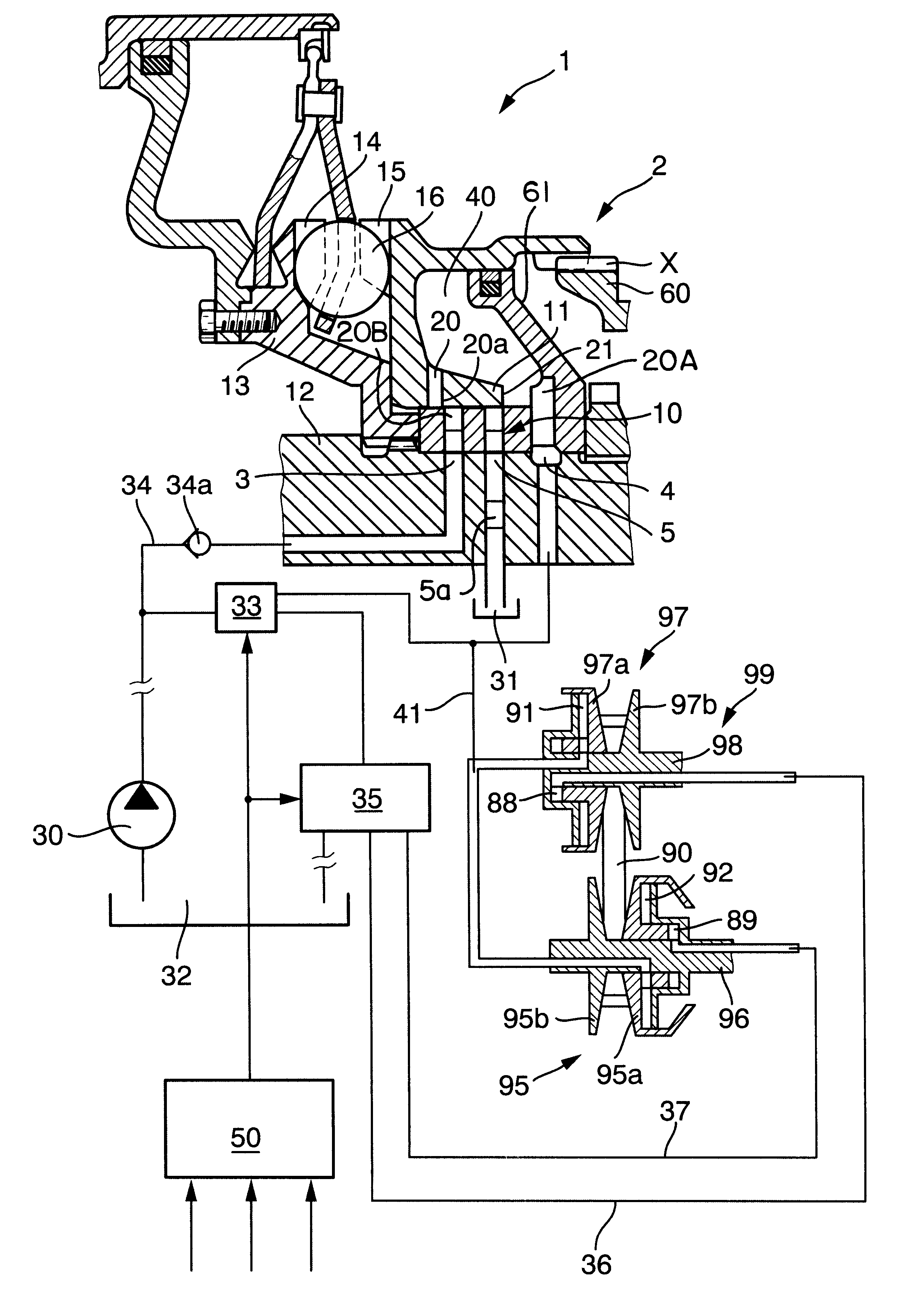
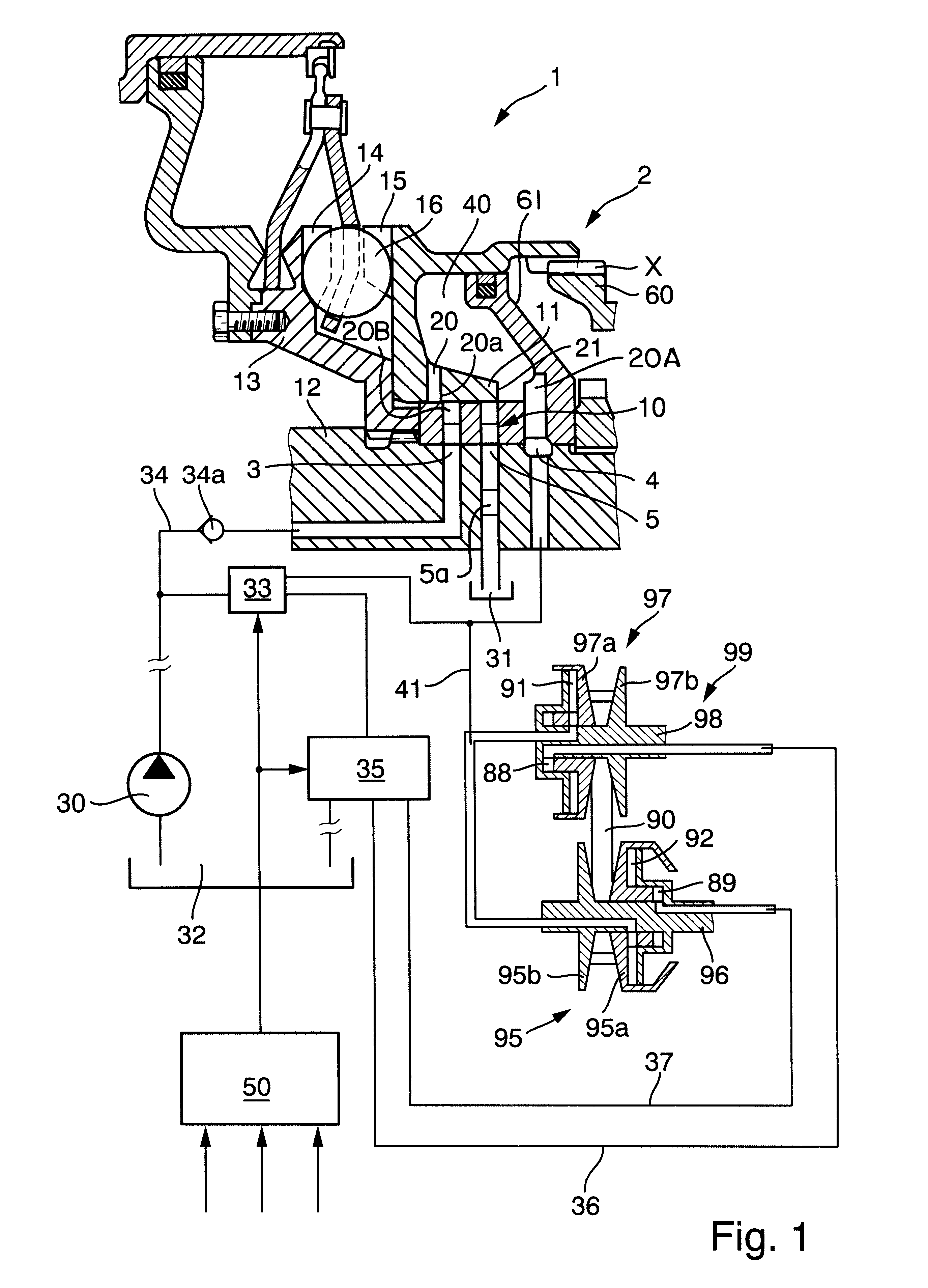
The invention is embodied in a rotary torque sensor which is arranged to transmit torque between rotary input and output elements, e.g., between a shaft which is driven by the camshaft or crankshaft of an internal combustion engine and a shaft which transmits torque to one adjustable pulley of a continuously variable transmission. The improved sensor has a plenum chamber and comprises a pressure reducing valve arranged to control the flow of a hydraulic fluid (e.g., oil) into and from the chamber. The valve has at least two valve members at least one of which is movable relative to the other valve member to thereby vary the pressure of fluid in the chamber and to thus influence the capacity of the torque sensor to transmit torque between the input and output elements. The torque sensor further comprises or cooperates with a pump or another suitable source of pressurized fluid which is connectable to the plenum chamber by the aforementioned valve.
Still further, it is possible to design the valve in such a way that, when the one valve member is moved relative to the other valve member to at least one preselected position, the inlet opening is sealed to prevent pressurized fluid from flowing from the source into the plenum chamber and the first outlet opening is also sealed to prevent fluid from flowing between the chamber and the fluid collecting device.
It is also possible to design the valve in such a way that the one valve member is movable relative to the other valve member to at least one position in which the inlet opening is sealed to prevent pressurized fluid from flowing from the source into the plenum chamber while the first outlet opening is at least partially exposed to permit fluid to flow between the chamber and the fluid collecting device.

Problems solved by technology

On the other hand, if the frictional engagement is insufficient, the flexible element and the pulleys are likely to slip relative to each other which entails unnecessary and highly pronounced wear affecting the useful life of the power train.

Method used


Image

  • Torque sensor for a motor vehicle power train
  • Torque sensor for a motor vehicle power train

Examples


Embodiment Construction

FIG. 1 shows a portion of a continuously variable transmission (CVT) 99 having a rotary driving unit and a rotary driven unit receiving torque from the driving unit by way of at least one endless flexible element 90 (e.g., a belt or a chain and hereinafter called chain). The driving unit comprises a shaft 98 and an adjustable pulley or sheave 97 having a first conical flange 97b affixed to the shaft 98 and a second conical flange 97a rotatable with and movable axially of the shaft 98 toward and away from the flange 97b. The driven unit of the transmission 99 comprises a rotary shaft 96 which is or which can be parallel to the shaft 98 and an adjustable pulley or sheave 95 composed of a first conical flange 95b affixed to the shaft 95 and a second conical flange 95a arranged to rotate with and being movable axially of the shaft 95 toward and away from the flange 95b. The chain 90 is trained over the pulleys 95 and 97.

The driving unit of the transmission 99 further comprises means for...


PUM


Abstract

A torque sensor between a rotary input element driven by an engine and a coaxial output element connected to a continuously variable transmission in the power train of a motor vehicle has a plenum chamber for a supply of hydraulic fluid. The chamber is defined by two coaxial valve members of a pressure reducing valve. One valve member is connected to the output element and is movable axially relative to the other valve member, which rotates with the input element, to change the fluid pressure in the chamber. An inlet opening of the valve serves to connect the chamber with the outlet of a pump which supplies pressurized fluid, and such opening is at least partially exposed in at least one first and sealed in at least one second position of the one valve member. A first outlet opening of of the valve can be exposed or sealed by the one valve member to respectively permit and prevent the flow of fluid between the chamber and a sump, and a second outlet opening of the valve serves to permit the flow of fluid from the chamber to one or more cylinder-and-piston units which regulate the operation of the transmission.

Description

The invention relates to improvements in apparatus for regulating the operation of certain constituents in the power trains of motor vehicles, for example, for regulating the operation of continuously variable transmissions in dependency upon the changes of one or more parameters of the motor vehicle, of its power train and / or other variables. Still more particularly, the invention relates to improvements in torque regulating apparatus which employ so-called torque sensors.Commonly owned U.S. Pat. No. 5,169,365 (granted Dec. 8, 1992 to Oswald Friedmann for "POWER TRAIN") discloses a power train wherein the engine of the motor vehicle transmits torque to a continuously variable transmission (CVT) by way of a rotary torque sensor which is connected to the output of a pump serving to supply a pressurized hydraulic fluid. The torque sensor acts as or includes a valve and serves to transmit torque from the engine to the input element of the transmission. As a rule, the valve of the torqu...

Claims


Application Information

Patent Timeline
IPC IPC(8): F16H61/66F16H61/662G01L3/02
CPCF16H61/66272
Inventor AGNER, IVO
Owner LUK GETRIEBE SYST
Learn More