Jewellery illumination

Inactive Publication Date: 2002-08-13
SCINTILLATE
View PDF15 Cites 94 Cited by
  • Summary
  • Abstract
  • Description
  • Claims
  • Application Information

AI Technical Summary

Benefits of technology

According to another broad aspect of the present invention there is provided an article of jewelry comprising: means for illuminating a jewel of the article; and a rechargeable power supply for powering the illuminating means. As mentioned previously, this has the advantage of avoiding the costly and laborious task of regular battery replacement. In addition, the battery capacity can be selected to last just a single wearing of the article and so the size of the battery can advantageously be minimized.
The rechargeable power supply is preferably arranged to receive power by indirect electrical connection to an external power source. Therefore, the need for electrical contacts between the article of jewelry and the external power source can be avoided. This in turn prevents the appearance of the article from being unattractively altered to accommodate the contacts.
According to another broad aspect of the present invention there is provided a method of illuminating a jewel for simulating natural optical effects of the jewel, such as sparkle and scintillation, the method comprising: pr

Problems solved by technology

Although jewel stones are generally designed to have optical effect, when external light is not strong enough, little optical effect including scintillation effect occurs and the colors of the jewel stones are not readily visible.
Further, when there is no relative movement between jewelry, the viewer and external light, jewel stones do not produce any optical effect even if enough ambient light is present.
In the prior art, the jewel illumination is at best rather crude.
In both GB 1 352 835 and U.S. Pat. No. 4,973,835, the pulsing of the LEDs is entirely dependent on external conditions s

Method used


Image

  • Jewellery illumination
  • Jewellery illumination
  • Jewellery illumination

Examples


second embodiment

Referring to FIGS. 12 and 13, an article of jewelry according to the present invention is shown. The article of jewelry 100 which is a ring in this embodiment, comprises a plurality of jewel stones 110 and a light source 120 incorporated in the article of jewelry 100.

Light emission from the light source 120 is controlled by an electronic system 130 which is also incorporated in the article of jewelry 100. The electronic system 130 of this embodiment comprises a controller 132, a timer 134, a detector 136, a switch 138 and a battery 140.

first embodiment

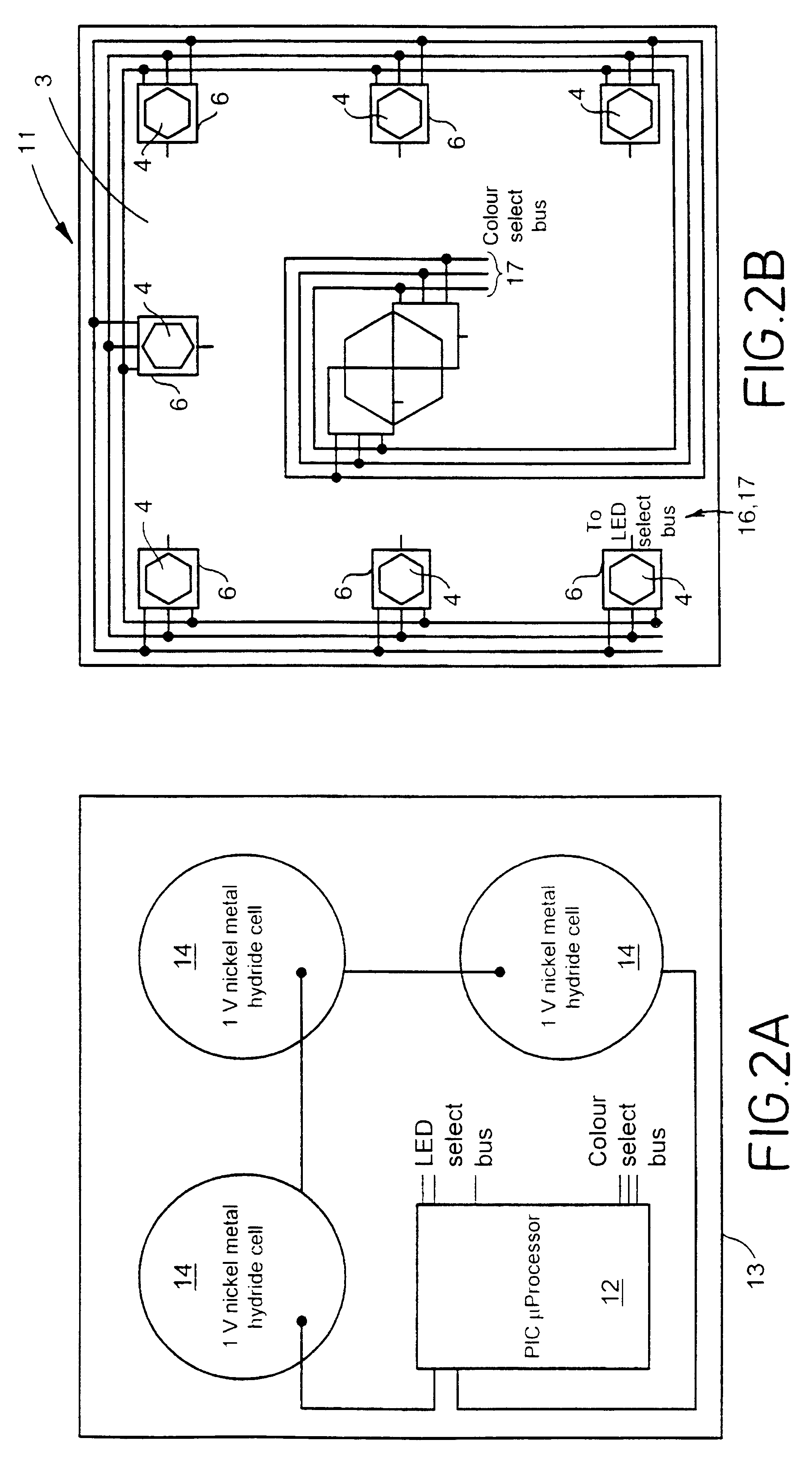
The control means 132 is a simple low-power microcontroller and can be the PIC microcontroller 12 of the first embodiment or an ASIC (Applications Specific Intergrated Circuit). The controller 132 is coupled to the light source 120 and controls patterns, amplitude and duration of the light emission pulses. The light pulses which are emitted are of variable intensity either by variation of the intensity along the duration of each light pulse and / or by variation of the peak light output intensity of each pulse successively along a sequence of pulses. Preferably, light pulse decay is simulated by having a succession of decreasing peak amplitude drive pulses. The basic frequency of light impulses is controlled using a signal from the timer 134. The detector 136 comprises a sensor which detects ambient temperature, ambient noise, ambient light, skin temperature and pulse rate of the wearer of the article of jewelry, or movement of the article of jewelry. It is possible to incorporate a p...

third embodiment

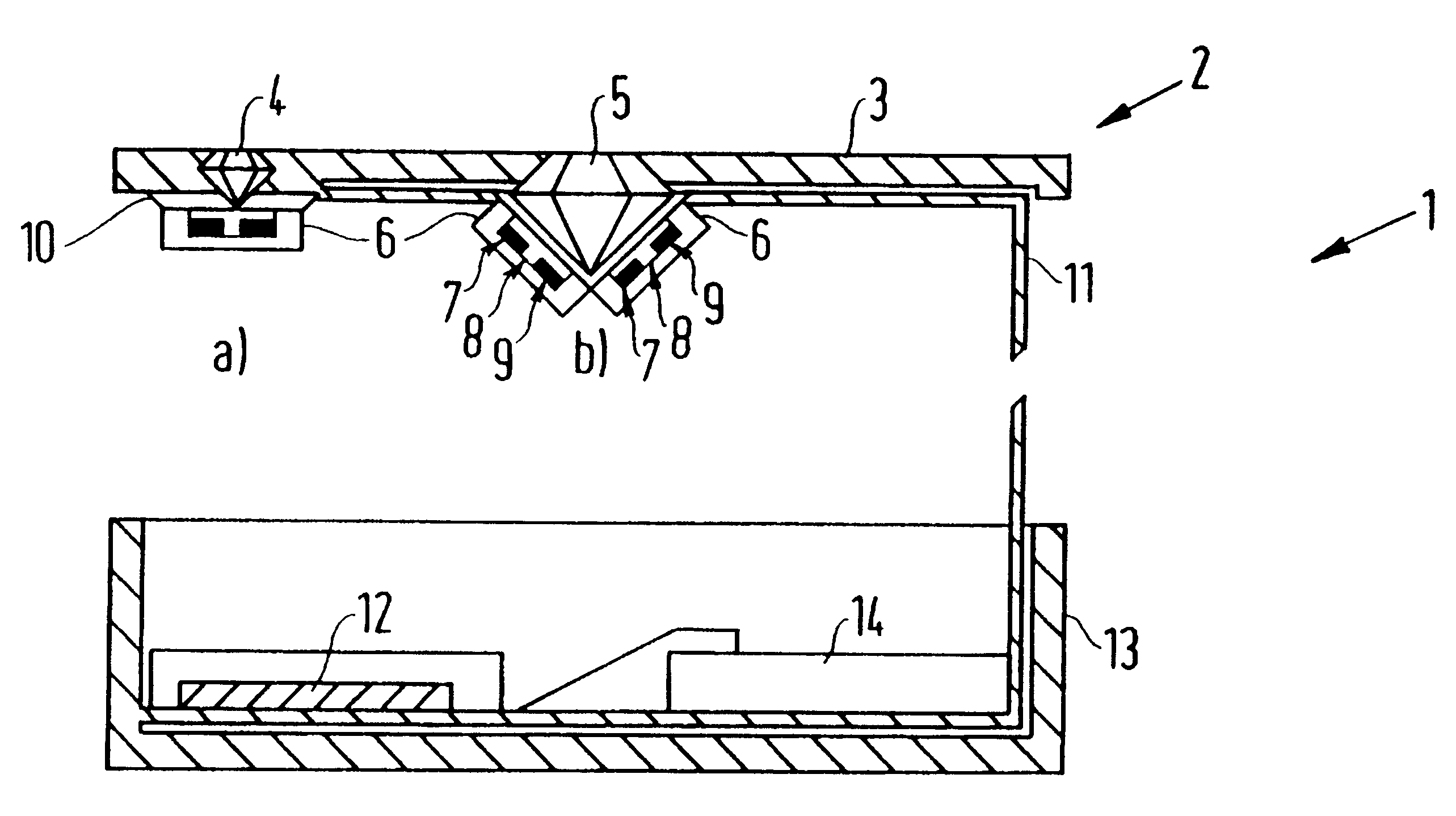
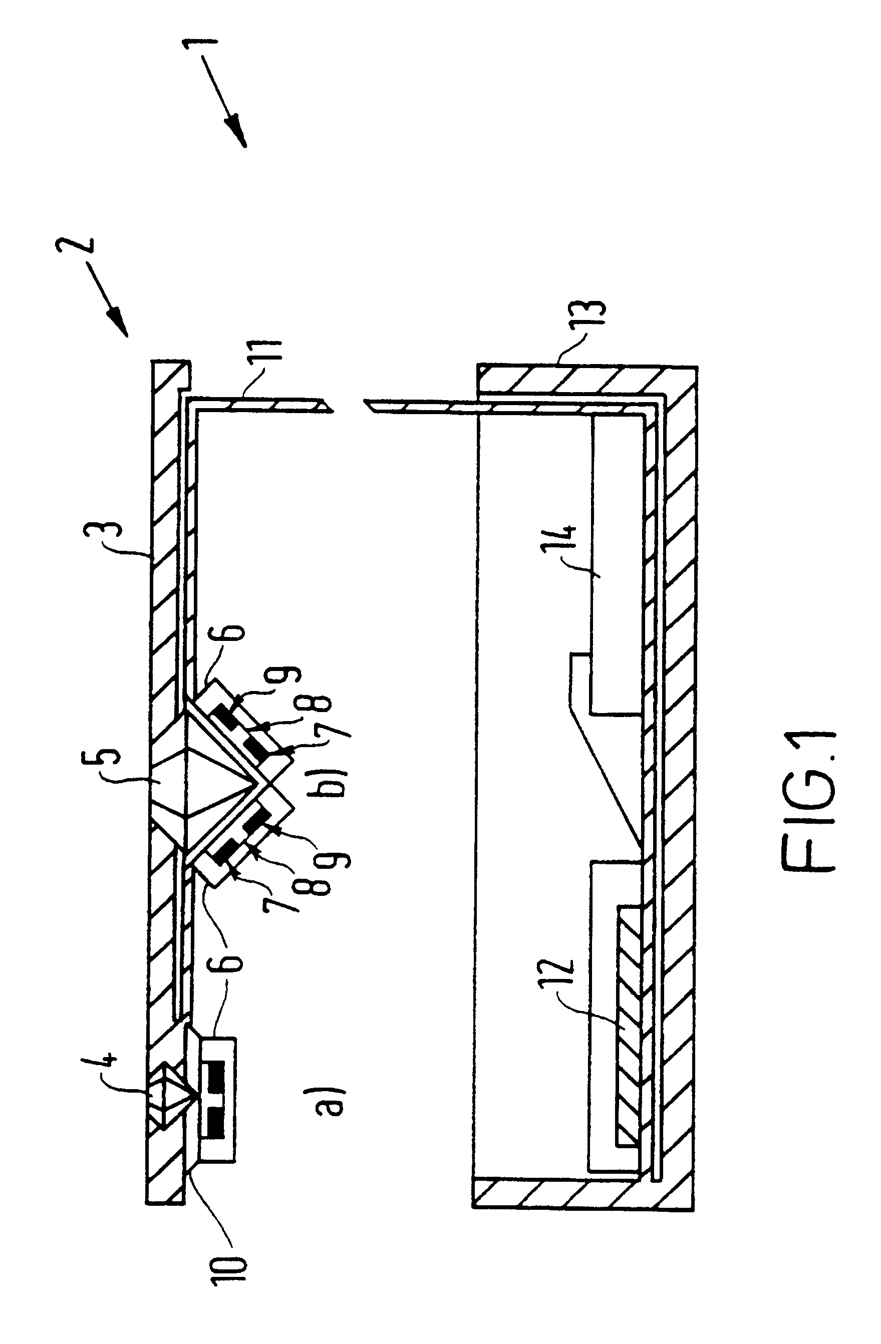
The module 300 of the third embodiment which is shown in FIGS. 14 and 15(a)-(d) is suitable for use as part of a brooch. The module 300 uses plug connections from a light source to individual jewels using optical fibers.

FIG. 13 depicts a rear surface of a base 160 of the module 300. The base 160 is provided with throughholes 162 in which jewel stones 164 are mounted so that they can be observed from the front side of the base 160, as shown in FIGS. 15(a)-(d). The base 160 is also provided with a recess 166 on the rear surface and a flange 168 at the peripheral of the base 160. In the recess 166, an ASIC 170 and an LED array 172 are provided.

The ASIC 170 is connected to an external battery 174 via an external power switch 176 for supply of electric power to the ASIC 170. The ASIC 170 is also connected to an external timing capacitor 178 and an environmental sensor (not shown). The battery 174, the power switch 176 and the timing capacitor 178 are accommodated in a space formed by the...


PUM


Abstract

An article of jewelry arranged to simulate natural optical effects, such as sparkle and scintillation, is described. The article comprises a jewel, such as a brilliant cut diamond and one or more light sources, such as colored LEDs, incorporated in the article of jewelry for emitting light so as to illuminate the jewel. The article also comprises a microcontroller for driving the one or more LEDs to cause them to emit light pulses of varying intensity thereby simulating said natural optical effects of the jewel. The duration of the light pulses and the location of each light pulse can be varied to enhance the artificial illumination. The article preferably has a cordless rechargeable power supply which avoids the need for unsightly electrical contacts by using an inductive loop charging circuit.

Description

The present invention concerns improvements relating to jewelry illumination, and more particularly, though not exclusively, relates to improvements concerning an article of jewelry including a jewel and having a light source incorporated in the article for illuminating the jewel.A jewel stone is an optical system that is manufactured from material that is not opaque to light. It may be a natural mineral or a manufactured artificial mineral or optical compound. The design is such that when illuminated and viewed from the front the light falling upon it is largely refracted, internally reflected and returned to the front so that the jewel stone appears bright. The refraction and reflection process may also change the color of the light emitted after passing through the jewel stone and re-emerging. Jewelry including one or more jewel stones is generally designed so that it does not pass light from the front to the rear. Thus when illuminated from the front and viewed from the rear, th...

Claims


Application Information

Patent Timeline
IPC IPC(8): A44C15/00
CPCA44C15/0015Y10S362/80Y10S362/806
Inventor MICHAEL, PETER COLINHOLMES, ANDREW SEANSYMS, RICHARD RODNEY ANTHONY
Owner SCINTILLATE
Why Eureka
Try Eureka