
Organic light emitting diode display device

a light-emitting diode and display device technology, applied in the direction of instruments, static indicating devices, etc., to achieve the effect of reducing battery consumption, minimizing power consumption, and reducing power consumption

Active Publication Date: 2018-02-13
LG DISPLAY CO LTD
View PDF7 Cites 6 Cited by
  • Summary
  • Abstract
  • Description
  • Claims
  • Application Information

AI Technical Summary

Benefits of technology

This approach reduces power consumption, minimizes luminance deviations, and extends the lifespan of OLED panels by compensating for TFT characteristic deviations and voltage drops, thereby enhancing image quality and reducing battery consumption.

Problems solved by technology

In recent years, while a demand for a wearable display device has rapidly increased, there has particularly been a new issue to minimize power consumption in the wearable display device having compact design.
Therefore, in driving an OLED display device having a compensation circuit in a pixel structure, the need to design the pixel structure and drive the OLED display device to minimize power consumption has been a key challenge.

Method used


Image

  • Organic light emitting diode display device
  • Organic light emitting diode display device
  • Organic light emitting diode display device

Examples


Embodiment Construction

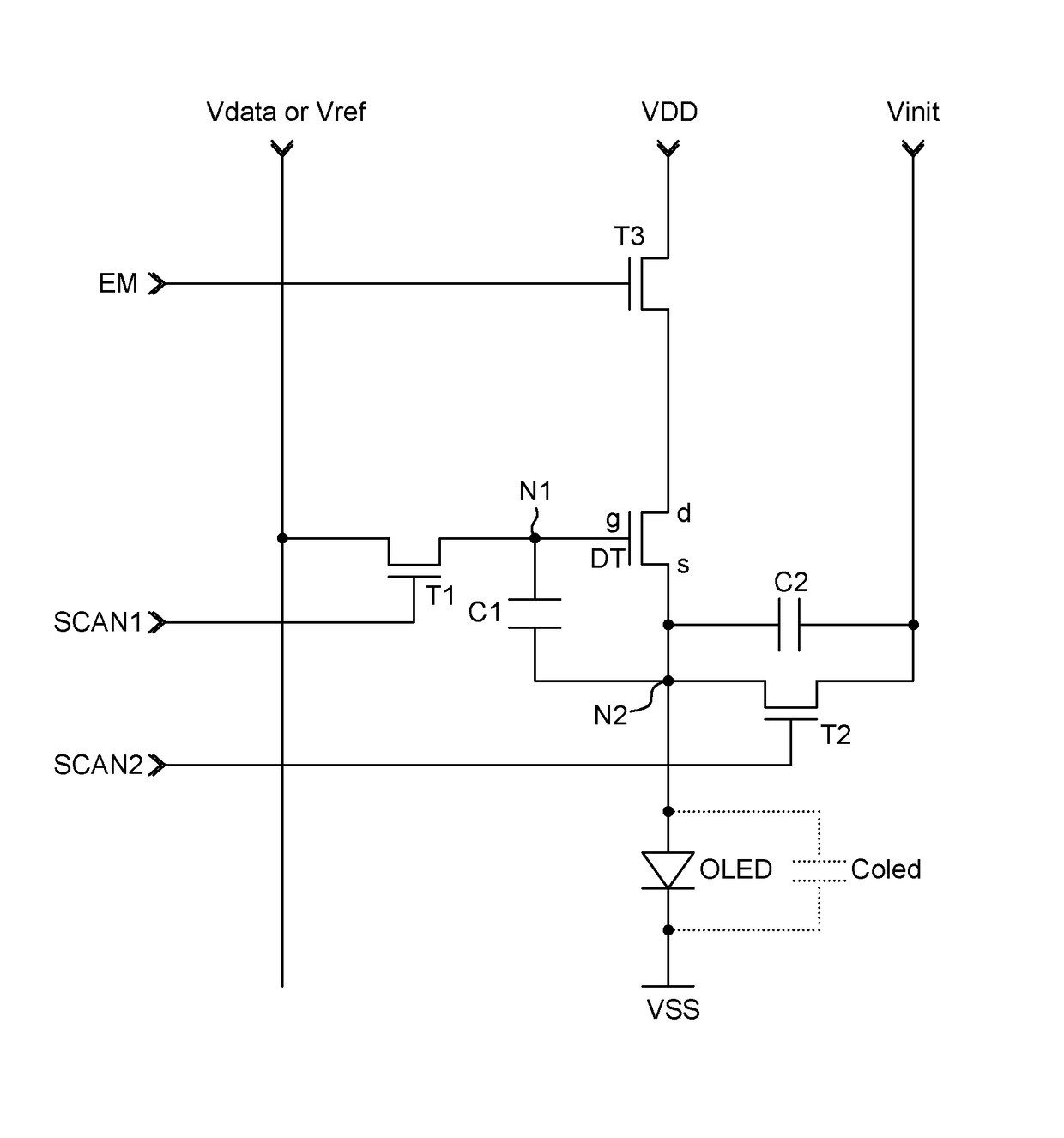
[0028]Hereinafter, an OLED display device and a driving method thereof according to exemplary embodiments of the present disclosure will be described in detail with reference to the accompanying drawings.

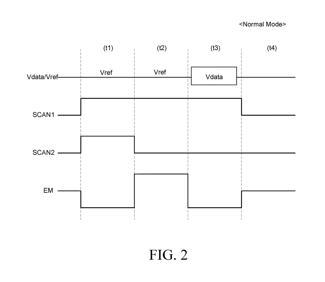
[0029]In the present disclosure, a TFT may be constituted by a P type or an N type and in the exemplary embodiments described below, it is described that the TFT is constituted by the N type for easy description. Therefore, a gate high voltage VGH as a voltage higher than threshold voltage of the TFT is a gate-on voltage to turn on the TFT and a gate low voltage VGL as a voltage lower than the threshold voltage of the TFT is a gate-off voltage to turn off the TFT. In addition, in describing a pulse type signal, a state of the gate high voltage VGH is defined as “high state” and a state of the gate low voltage VGL is defined as “low state”.

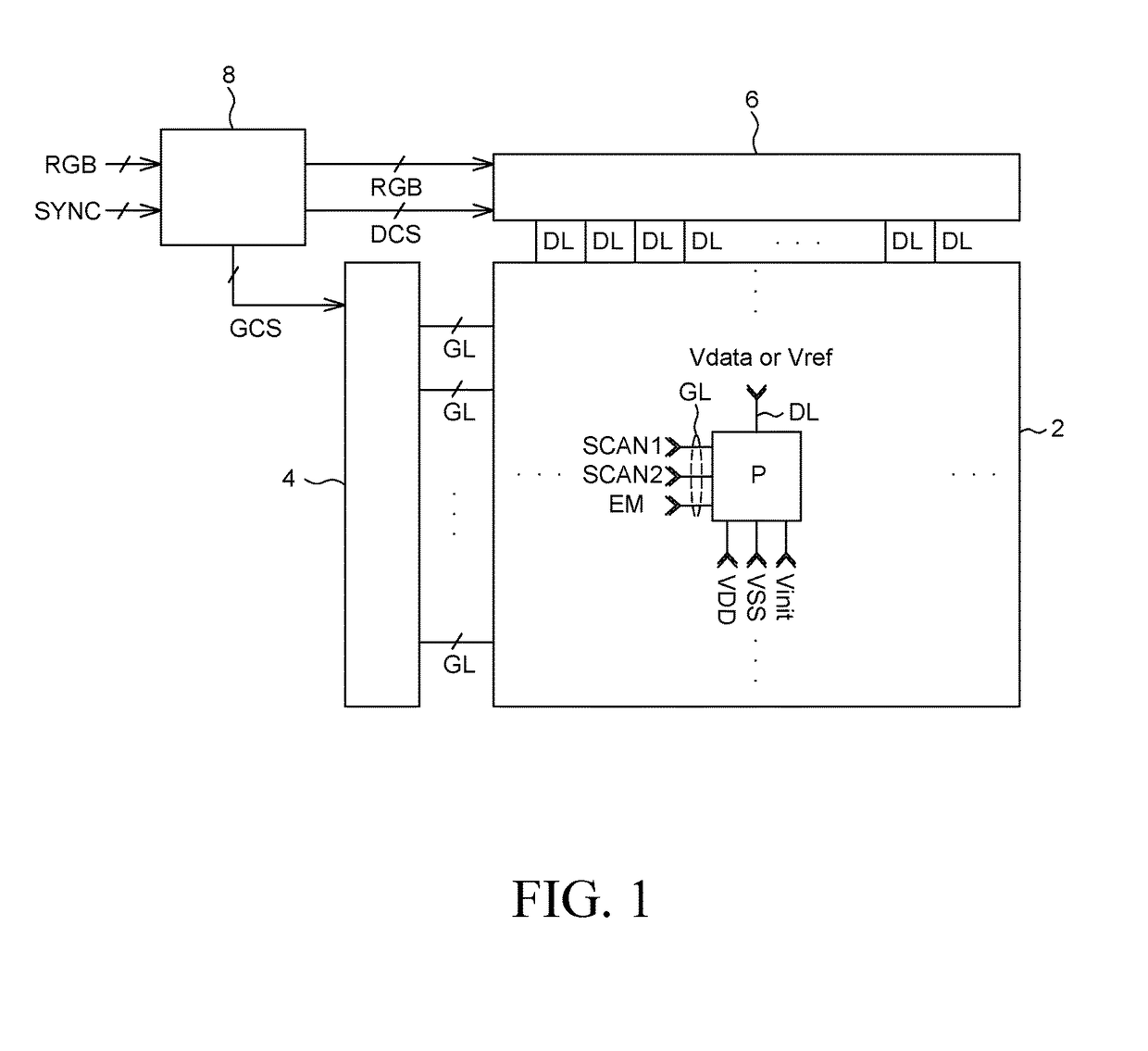
[0030]FIG. 1 is a configuration diagram of an organic light emitting diode (OLED) display device according to an exemplary embodiment of the prese...


PUM


Abstract

Provided is an OLED display device that is in a black mode in which a threshold voltage of a driving TFT need not accurately be sensed. Further, a low voltage value of zero or less is constantly and continuously supplied to a data line during an initialization period, a sampling period, and a programming period in a pixel. As a result, when the pixel is driven in the black mode, a reference voltage and a data voltage having different values are not alternately supplied to the data line to minimize power consumption.

Description

CROSS-REFERENCE TO RELATED APPLICATIONS[0001]This application claims the priority of Korean Patent Application No. 10-2014-0177877 filed on Dec. 10, 2014, in the Korean Intellectual Property Office, the disclosure of which is incorporated herein by reference.BACKGROUND OF THE INVENTION[0002]Field[0003]The present disclosure relates to an organic light emitting diode (hereinafter, referred to as OLED) display device.[0004]Description of the Related Art[0005]Each of a plurality of pixels constituting an OLED display device includes an OLED which includes an anode, a cathode, and organic light emitting layers in between the anode and the cathode, and a pixel circuit independently driving the OLED. The pixel circuit primarily includes a switching thin film transistor (hereinafter, referred to as TFT), a capacitor, and a driving TFT. The switching of TFT charges data voltage in the capacitor in response to a scan pulse, and the driving of TFT controls an electric current amount supplied ...

Claims


Application Information

Patent Timeline
Patent Type & Authority Patents(United States)
IPC IPC(8): G09G3/3225
CPCG09G3/3225G09G2300/043G09G2300/0819G09G2300/0861G09G2310/0243G09G2330/021G09G2320/0233G09G2320/0238G09G2320/045G09G2320/0626G09G2310/0262G09G2300/0852H10K59/84H10K59/86H10K59/00
Inventor SONG, JANGHOONJEONG, SEOKHEEKANG, CHANGHEONLEE
Owner LG DISPLAY CO LTD
Learn More