Surface light source device of side light type

a technology of surface light source and side light, which is applied in the direction of lighting and heating equipment, instruments, machines/engines, etc., can solve the problem of reducing and achieve the effect of improving the uniformity of output light and preventing bright lines

Inactive Publication Date: 2002-08-20
ENPLAS CORP
View PDF6 Cites 42 Cited by
  • Summary
  • Abstract
  • Description
  • Claims
  • Application Information

AI Technical Summary

Benefits of technology

An object of the present invention is to provide a surface light source device of side light type with improved uniformity of output light by preventing bright lines from being generated on a guide plate.
In accordance with features of the present invention, at least one of the additive members has a shield for preventing illuminating light from being incident to the first or second edge.

Problems solved by technology

However, an undesirable bright line appears on the guide plate 2 in the conventional device explained above so that uniformity of output light is reduced.

Method used


Image

  • Surface light source device of side light type
  • Surface light source device of side light type
  • Surface light source device of side light type

Examples


first embodiment

(1) First Embodiment

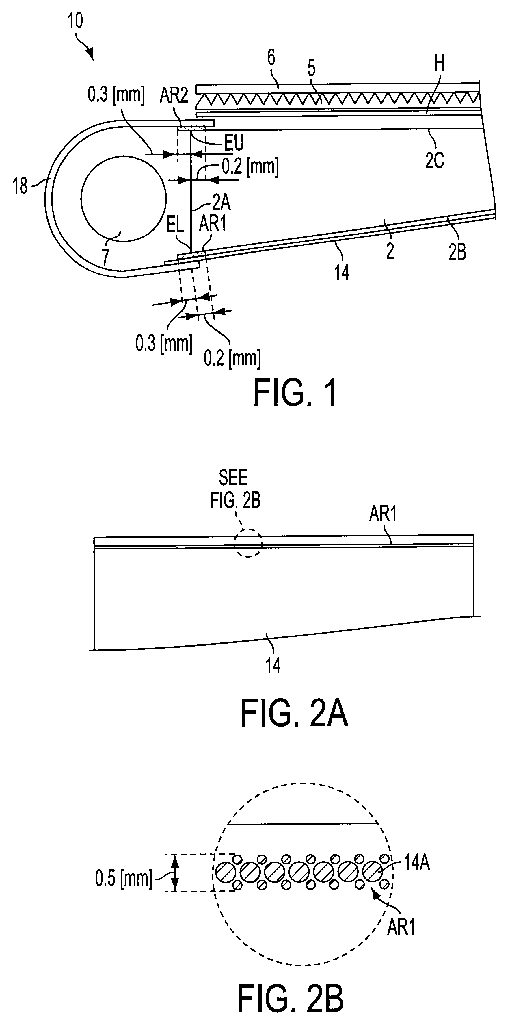
A first embodiment will next be explained with reference to FIGS. 1 and 2. In the figures and the explanation, elements employed commonly to the prior art (FIGS. 8 and 9) are designated by common reference numerals. Further, repeating of explanation is minimized in the following description.

With reference to FIGS. 1 and 2, a surface light source device 10 of side light type has a guide plate 2, a primary light source 3 (a fluorescent lamp 7 and a reflector 18), a reflection sheet 14, a light diffusive sheet H and prism sheets 5, 6. The reflector 18, the reflection sheet 14, the light diffusive sheet H and the prism sheets 5, 6 are additive members. The guide plate 2 has a back surface 2B and an emission surface 2C as major surfaces.

A regular reflection member evaporating silver on a base sheet is adopted in the reflection sheet 14 to show high reflectivity with respect to illuminating light. The reflection sheet 14 efficiently returns illuminating light leaked fr...

second embodiment

(2) Second Embodiment

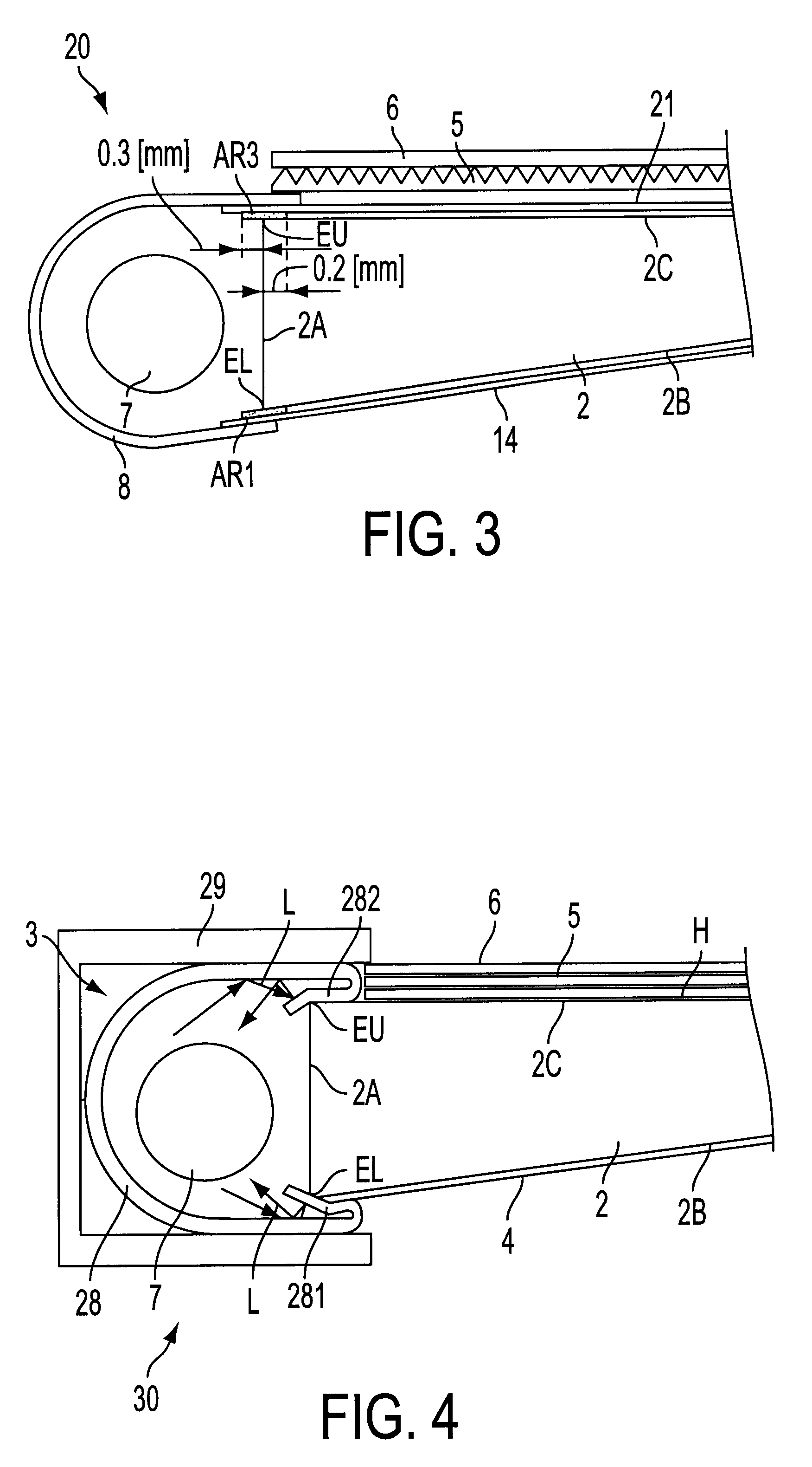
A second embodiment will next be explained with reference to FIG. 3. The embodiment has a structure common to the first embodiment except for around an upper side of the incident surface of the guide plate. Accordingly, elements employed commonly to the first embodiment (FIGS. 1 and 2) are designated by common reference numerals in the following illustration and explanation. Further, an overlapping explanation is minimized in the following description.

With reference to FIG. 3, a surface light source device 20 of side light type has a guide plate 2, a primary light source 3 (a fluorescent lamp 7 and a reflector 8), a reflection sheet 14, a light diffusive sheet 21 and prism sheets 5, 6. The reflector 8, the reflection sheet 14, the light diffusive sheet 21 and the prism sheets 5, 6 are additive members. The guide plate 2 has a back surface 2B and an emission surface 2C as major surfaces.

A regular reflection member evaporating silver on a base sheet is adopted in ...

third embodiment

(3) Third Embodiment

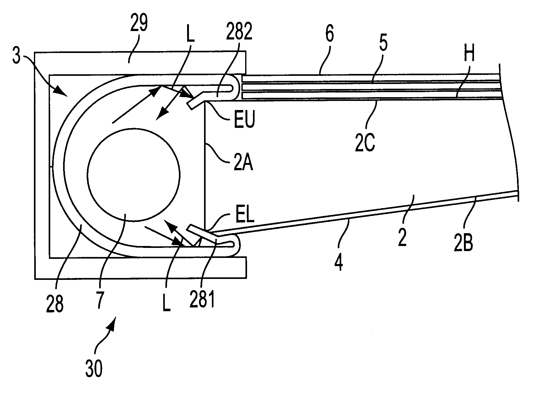
A third embodiment will next be explained with reference to FIG. 4. The embodiment has a structure common to the first and second embodiments except for the upper and lower sides of the incident surface of the guide plate. Accordingly, elements employed commonly to the first embodiment (FIGS. 1 and 2) or the second embodiment (FIG. 3) are designated by common reference numerals in the following illustration and explanation. Further, an overlapping explanation is minimized in the following description.

With reference to FIG. 4, a surface light source device 30 of side light type has a guide plate 2, a primary light source 3 (a fluorescent lamp 7 and a reflector 28), a reflection sheet 4, a light diffusive sheet H, prism sheets 5, 6 and a frame 29. The reflector 28, the reflection sheet 4, the light diffusive sheet H, the prism sheets 5, 6 and the frame 29 are additive members. The guide plate 2 has a back surface 2B and an emission surface 2C as major surfaces.

A re...


PUM

PropertyMeasurementUnit
widthaaaaaaaaaa
widthaaaaaaaaaa
lengthsaaaaaaaaaa

Abstract

A surface light source device of side light type has a guide plate, a primary light source for supplying illuminating light through an incidence surface, first and second edges at which major surfaces respectively intersect the incidence surface, and one or plural additive members arranged in direct contact with the emission surface and / or the back surface thereon in the vicinity of the first edge and / or the second edge. At least one of the additive members has a shield for preventing illuminating light from being incident to the first or second edge. For example, the shield includes absorptive areas formed on the additive members. Each of the absorptive areas is formed so that each of the absorptive areas crosses the first or second edge. A distal end of a reflector arranged in the primary light source or frame blocks incidence of light to the first and / or second edge. The light incidence block to each edge prevents luminance irregularities in the form of a bright line.

Description

1. Field of InventionThe present invention relates to a surface light source device of side light type, and more particularly to a technique for improving uniformity of output light in the surface light source device. The present invention is applied, for example, to backlighting for a liquid crystal display.2. Related ArtA surface light source device of side light type is conventionally applied to a liquid crystal display to illuminate a liquid crystal panel from its back surface. The arrangement is suitable for making an entire shape of the surface light source device thin.A bar-shaped light source such as a cold cathode tube, etc. is generally adopted as a primary light source in the surface light source device of side light type and is arranged on the side of a guide plate (a guide body formed in a plate shape). Illuminating light emitted from the primary light source is introduced into the guide plate through a side end surface of the guide plate. The introduced illuminating li...

Claims


Application Information

Patent Timeline
Patent Type & Authority Patents(United States)
IPC IPC(8): F21V8/00G02B6/00G02F1/1335G02F1/13357
CPCG02B6/0031G02B6/005G02B6/0043G02B6/0055G02B6/0071G02B6/0088
Inventor MATSUSHITA, HIROMI
Owner ENPLAS CORP
Why Eureka
Try Eureka