System and method for accessing object capabilities in a graphical program

a graphical program and object capability technology, applied in the field of high-level text-based programming languages, can solve the problems of complex task of programming a computer system to model a process, limiting the achievement of optimal utilization of the computer system, and not fully proficient in techniques

Inactive Publication Date: 2002-08-20
NATIONAL INSTRUMENTS
View PDF40 Cites 446 Cited by
  • Summary
  • Abstract
  • Description
  • Claims
  • Application Information

AI Technical Summary

Problems solved by technology

When traditional text-based programming environments are used, the user's programming skills and ability to interact with the computer system often become a limiting factor in the achievement of optimal utilization of the computer system.
There are numerous subtle complexities which a user must master before he / she can efficiently program a computer system in a text-based environment.
The task of programming a computer system to model a process often is further complicated by the fact that a sequence of mathematical formulas, mathematical steps or other procedures customarily used to conceptually model a process often does not closely correspond to the traditional text-based programming techniques used to program a computer system to model such a process.
Since a user often is not fully proficient in techniques for programming a computer system in a text-based environment to implement his model, the efficiency with which the computer system can be utilized to perform such modeling often is reduced.
Traditional users of these systems, however, often were not highly trained in programming techniques and, in addition, traditional text-based programming languages were not sufficiently intuitive to allow users to use these languages without training.
Therefore, implementation of such systems frequently required the involvement of a programmer to write software for control and analysis of instrumentation or industrial automation data.
Thus, development and maintenance of the software elements in these systems often proved to be difficult.

Method used


Image

  • System and method for accessing object capabilities in a graphical program
  • System and method for accessing object capabilities in a graphical program
  • System and method for accessing object capabilities in a graphical program

Examples


first embodiment

FIGS. 8-36: First Embodiment

Graphical Program Client Creation

FIG. 8 is a flowchart illustrating steps taken to create a graphical program, referred to as a graphical program client or graphical automation client, according to the preferred embodiment of the method. The flowchart of FIG. 8 provides a high level view of the method of the preferred embodiment. The flowchart of FIGS. 8a-8c provide a more detailed view of the method of this embodiment. Thus the flowchart of FIG. 8 provides a high level view of the steps of the flowchart of FIGS. 8a, 8b, and 8c, and corresponding steps are numbered identically. The screen shot of FIG. 6 illustrates an example graphical program created according to the flowchart of FIG. 8. The nodes illustrated in FIG. 7 are example object nodes, referred to as automation function nodes, which are used in the flowchart of FIG. 8. In this description, the terms "automation" and "object" are used substantially interchangeably.

As shown in FIG. 8, the user dro...

second embodiment

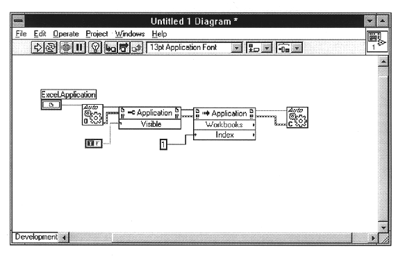
FIGS. 37-52: Second Embodiment

FIGS. 37-52 illustrate a second embodiment of the present invention. This second embodiment is a specific embodiment of FIGS. 8-36, where the object whose capabilities are being accessed is an application, such as a graphical program application, e.g., LabVIEW. In this embodiment, the object node is referred to as a "call by reference node". The call by reference node is essentially an invoke node as described above which can invoke or call only a run method on an application. Thus a call by reference node is a specific implementation or subset of the invoke node. It is noted that either an invoke node or a call by reference node may be used in this embodiment, as desired.

FIG. 37--Graphical Programming Environment

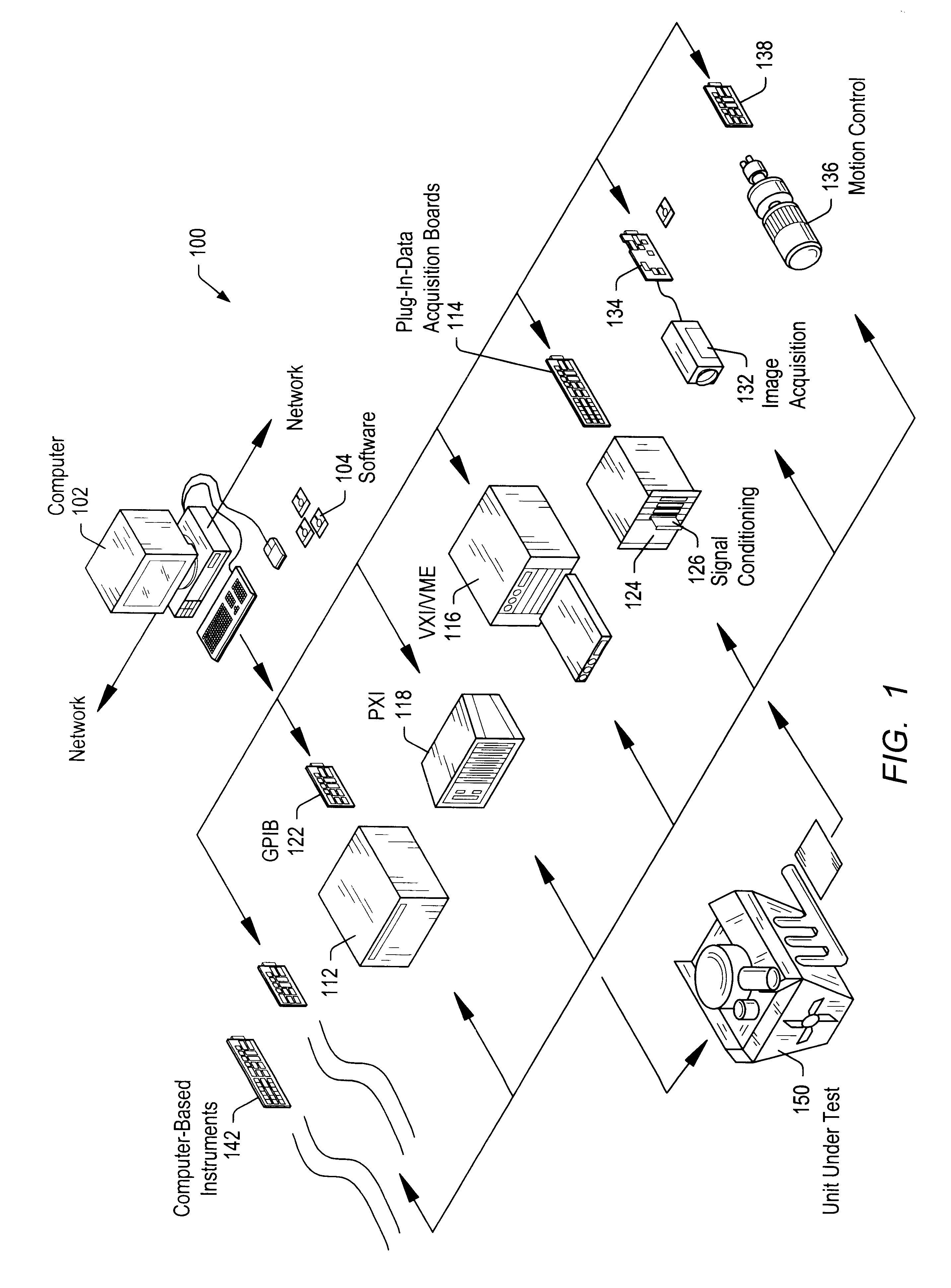
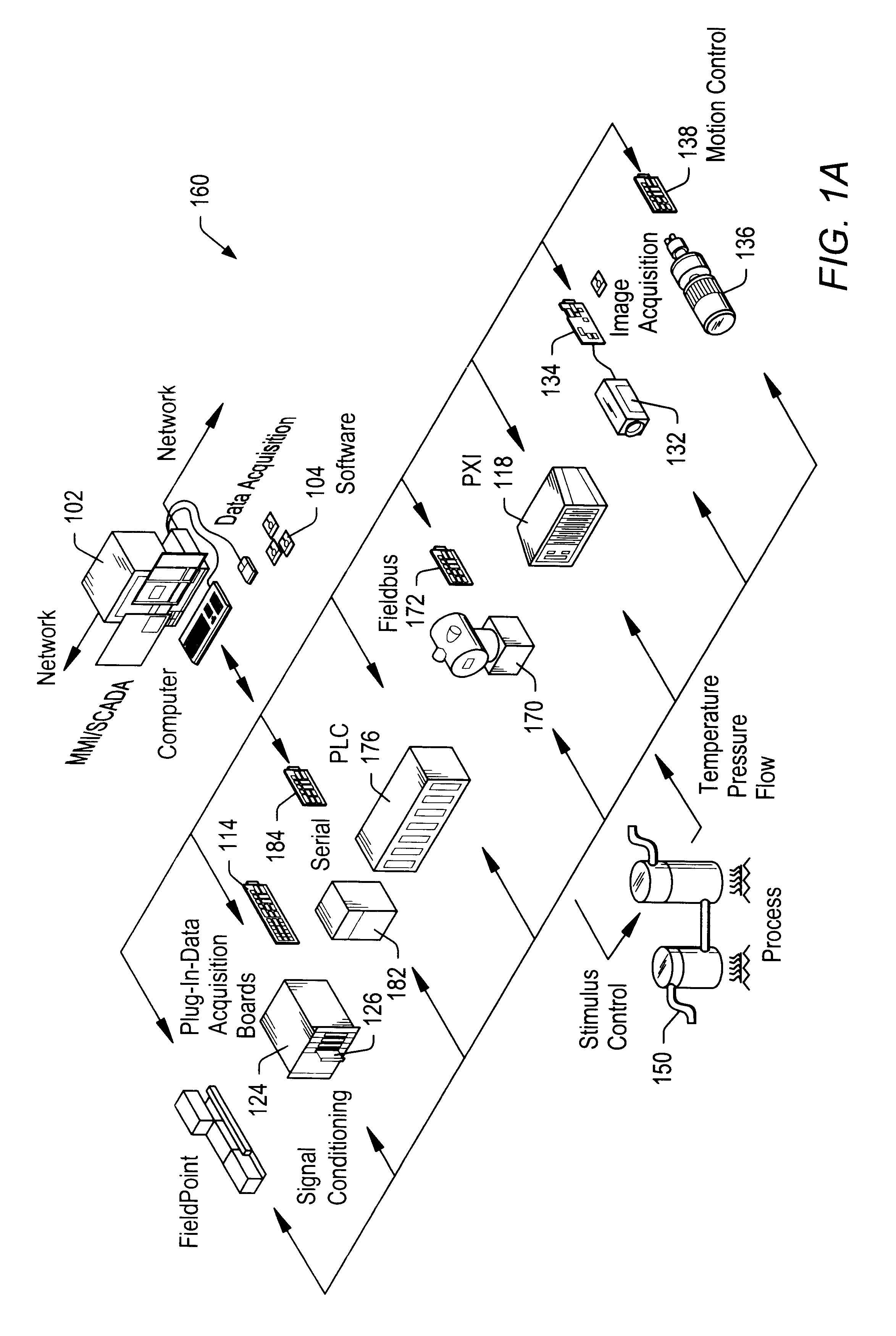
FIG. 37 is a block diagram illustrating the relationship of portions of the instrumentation control system 100 and 160 (of FIGS. 1 and 1A). FIG. 37 is similar to FIG. 3 described above, with changes to certain names of the software blocks to il...

third embodiment

FIGS. 51-54: Third Embodiment

FIGS. 51-54 illustrate a third embodiment where the object node comprises a user interface node which manipulates data on objects comprised in the node. In the preferred embodiment, the user interface object node is an ActiveX container.

ActiveX Front Panel Enhancements

In this embodiment, the graphical programming system, e.g., LabVIEW, includes a new control subpalette for the front panel, the Ctls subpalette, which includes two ActiveX controls: ActiveX Container and Active X Variant, as shown in FIG. 51.

These new controls allow the user to take advantage of the ActiveX Container capability, and enhance the interactions between LabVIEW and other applications.

ActiveX Variant Control and Indicator

The ActiveX Variant control and indicator allows passage of Active X Variant data into LabVIEW, so ActiveX client functionality is enhanced. This front panel object is used when ActiveX Variant data is converted to data that LabVIEW can display.

ActiveX Container

T...


PUM


Abstract

A system and method for creating a graphical program, wherein the graphical program is operable to access capabilities of an object. During creation of the graphical program, the user operates to place an object node in the graphical program, wherein the object node is operable to access capabilities of the object. This preferably includes the user arranging on the screen the graphical program, including the object node and various other nodes, and connecting the various nodes to create the graphical program. The user then configures the object node to receive information on the object, preferably by the user configuring the object node with a reference to the object, e.g., a pointer, address, or other information which specifies the identity and/or location of the object. The user also selects one or more methods to be invoked on the object and/or one or more properties to get/set on the object. Once the graphical program has been created, then during execution of the graphical program, the object node accesses the capabilities of the object.

Description

RESERVATION OF COPYRIGHTA portion of the disclosure of this patent document contains material to which a claim of copyright protection is made. The copyright owner has no objection to the facsimile reproduction by anyone of the patent document or the patent disclosure as it appears in the Patent and Trademark Office patent file or records, but reserves all other rights whatsoever.The present invention relates to graphical programming, and in particular to a system for creating graphical programs, wherein the graphical programs are operable to access functionality or properties of objects.DESCRIPTION OF THE RELATED ARTTraditionally, high level text-based programming languages have been used by programmers in writing applications programs. Many different high level programming languages exist, including BASIC, C, FORTRAN, Pascal, COBOL, ADA, APL, etc. Programs written in these high level languages are translated to the machine language level by translators known as compilers. The high...

Claims


Application Information

Patent Timeline
Patent Type & Authority Patents(United States)
IPC IPC(8): G09G5/00
CPCG05B19/0426G06F8/34G05B2219/23008G05B2219/23258
Inventor SOJOODI, OMIDDYE, ROBERTPARTHASARATHY, MURALIKUDUKOLI, RAM
Owner NATIONAL INSTRUMENTS
Why Eureka
Try Eureka