Reduction of electromagnetic emission

Inactive Publication Date: 2002-08-20
TELEFON AB LM ERICSSON (PUBL)
View PDF6 Cites 6 Cited by
  • Summary
  • Abstract
  • Description
  • Claims
  • Application Information

AI Technical Summary

Problems solved by technology

However, neither this publication nor the previously discussed U.S. Pat. No. 5,431,697 disclose dynamic timer

Method used


Image

  • Reduction of electromagnetic emission
  • Reduction of electromagnetic emission
  • Reduction of electromagnetic emission

Examples


Embodiment Construction

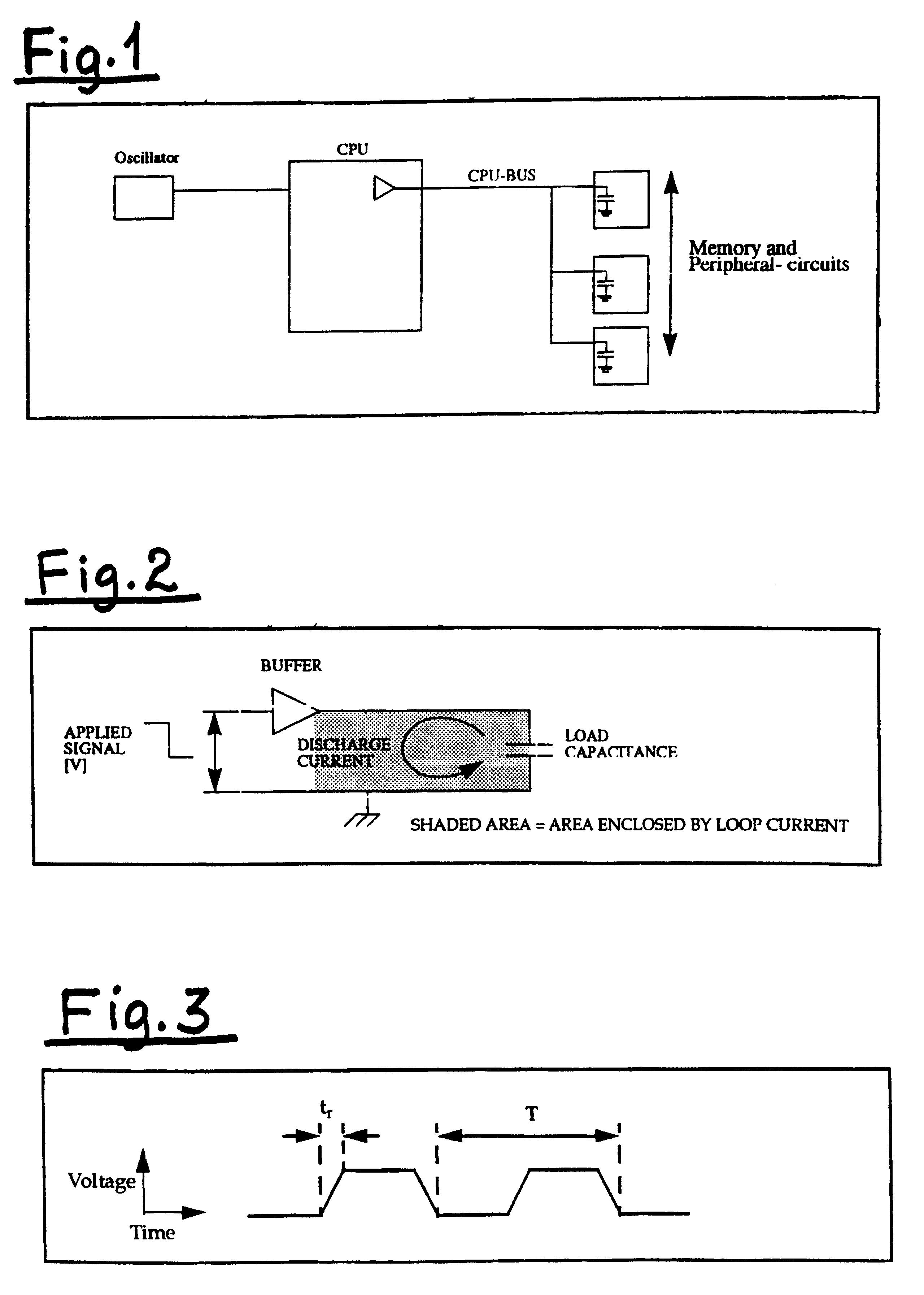
For the sake of giving a short summary of the mechanisms behind the emission of differential mode radiation from a signal line, reference should be made to FIGS. 1, 2 and 3, wherein FIG. 1 is a schematical block diagram illustrating a simplified CPU system and driver stage, FIG. 2 is a simplified diagram for a driver stage with a negative edge signal, and FIG. 3 illustrates a typical signal.

It is to be understood that the emitted radiation from a signal line is proportional to the fundamental frequency of the signal driving that line.

With specific reference to FIG. 1 it should be noted that each of the drivers on the CPU bus will carry currents to charge and discharge the capacitive load on the bus. In FIG. 2 there is illustrated one driver stage and the current that flows as the capacitor in the illustrated case is discharged.

The signal which is applied to the signal line will have a set of frequency components according to the signal characteristics. A typical signal is illustrate...


PUM


Abstract

The present invention relates to a method for reducing electromagneic emission, especially in connection with high-performance real-time systems, and more specifically for complying with the EMC (ElectroMagnetic Compatibility) thereof, and in order to acheive a reduced electromagnetic emission, it is according to the invention suggested to control the access to the CPU (Central Processing Unit) bus for thereby through power-down to reduce said bus-activity and thereby reduce the electromagnetic emission therefrom.

Description

The present invention relates to reduction of electromagnetic emission, and more specifically to a method for reducing electromagnetic emission, especially in connection with high-performance real-time systems, and for complying with the EMC (ElectroMagnetic Compability) requirements thereof.HISTORY OF THE RELATED ARTFrom U.S. Pat. No. 5,297,275 (Thayer) there is known a personal computer system comprising variable resolution timers, in which said variable resolution timers are set for the occurrence of the next timer tick interrupt. This arrangement prevents the central processing unit from being loaded unnecessarily with such interrupts, and thereby release processor capacity for other tasks. According to this publication it is also disclosed how the use of dynamic timer ticks can result in the receipt of timer tick interrupts in the central processing unit only at points in time at which this will result in the central processing unit performing a task.However, from said U.S. pub...

Claims


Application Information

Patent Timeline
IPC IPC(8): G06F1/32
CPCG06F1/3203G06F1/325
Inventor HELLUM, P.ANG.L LONGVA
Owner TELEFON AB LM ERICSSON (PUBL)
Why Eureka
Try Eureka