Method of detecting failure of a servo-valve, and a servo-valve applying the method

a technology of servo valves and servo valves, applied in the direction of dynamo-electric machines, gas/liquid distribution and storage, water mains, etc., can solve the problems of electromagnetic torque being applied to the rotor and the rotor engaging a stop

Active Publication Date: 2013-04-11
SAFRAN AEROSYSTEMS HYDRAULICS
View PDF122 Cites 14 Cited by
  • Summary
  • Abstract
  • Description
  • Claims
  • Application Information

AI Technical Summary

Benefits of technology

[0023]The method is based on detecting a discrete state: the rotor engaging a stop. This type of state can be detected by means that are simple, such as dry contacts or contactless sensors (e.g. of the magnetic type). Those detection means are selected depending on the nature of the detection circuit that is to be implemented, in particular in terms of its sensitivity to being disturbed by its surroundings or of the capacities of the computer to process the signal that is generated. The simplicity of these means may also have an effect of improving the reliability of the device, and also of reducing its cost and weight. It is possible to fit an existing servo-valve with a device that is particularly robust and reliable and that is suitable for generating a malfunction signal that is clear and fast, for little extra cost and extra weight.

Problems solved by technology

The inventors have observed that faulty operation of a servo-valve usually leads to the rotor of the torque motor engaging a stop.
This gives rise to an electromagnetic torque being applied to the rotor so long as the hydraulic element has not performed the desired movement.

Method used


Image

  • Method of detecting failure of a servo-valve, and a servo-valve applying the method
  • Method of detecting failure of a servo-valve, and a servo-valve applying the method
  • Method of detecting failure of a servo-valve, and a servo-valve applying the method

Examples


Embodiment Construction

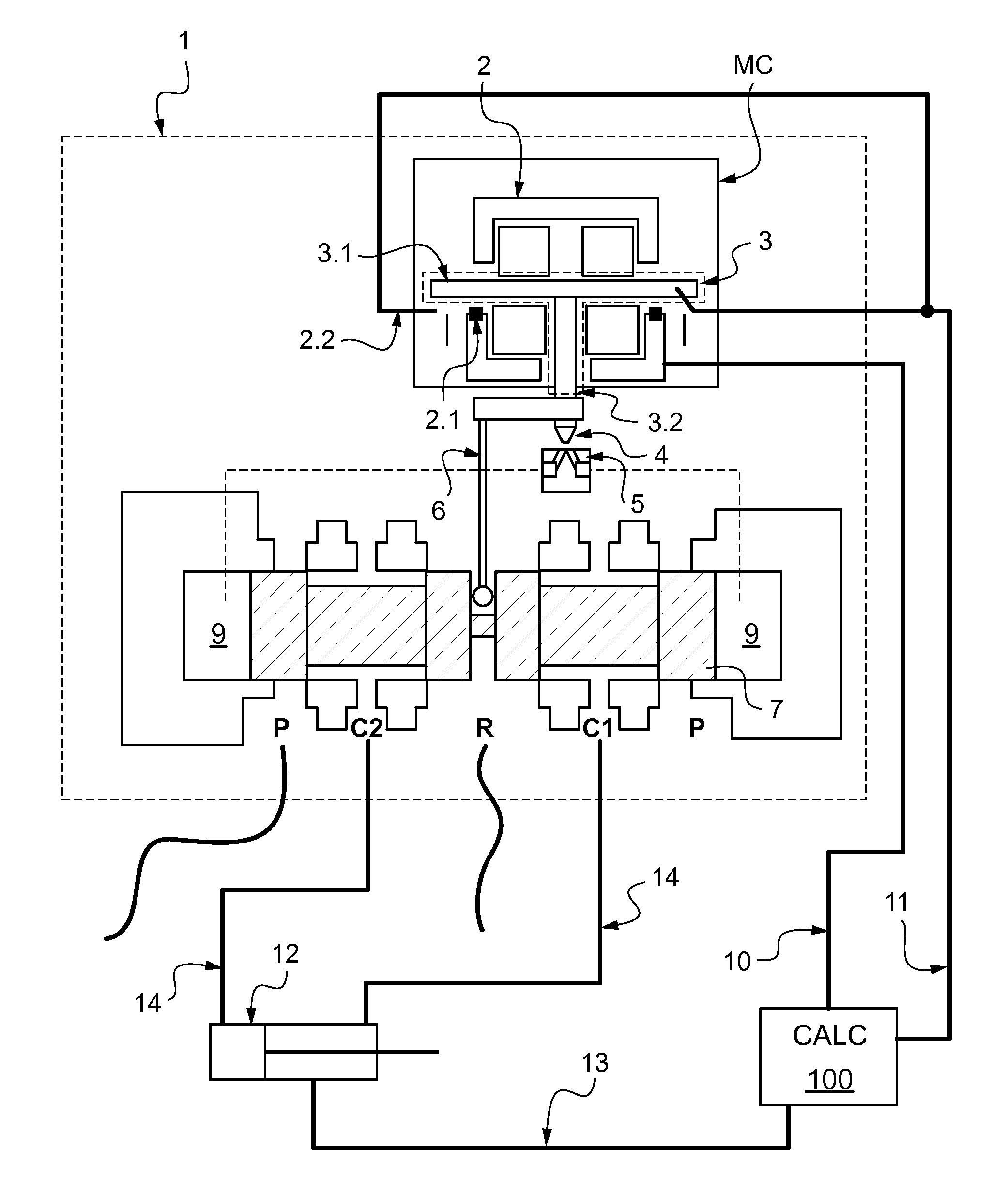
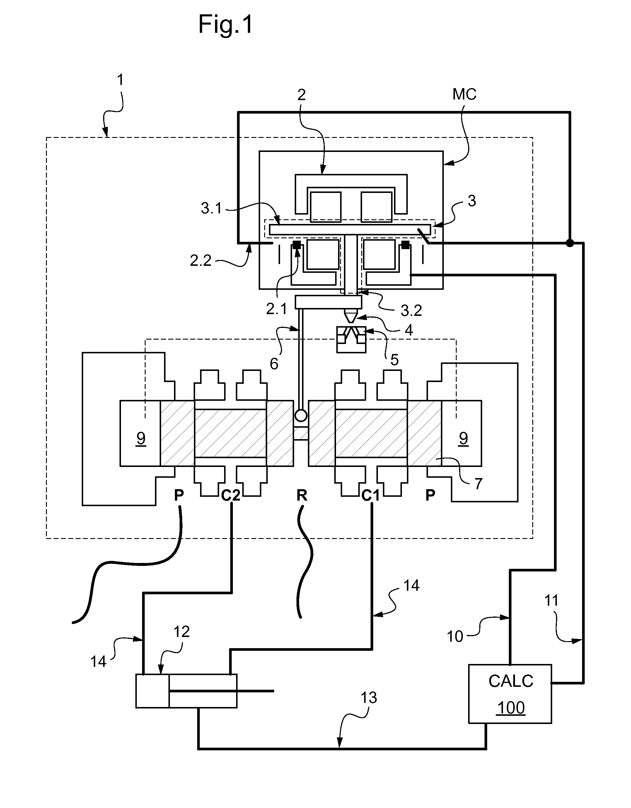
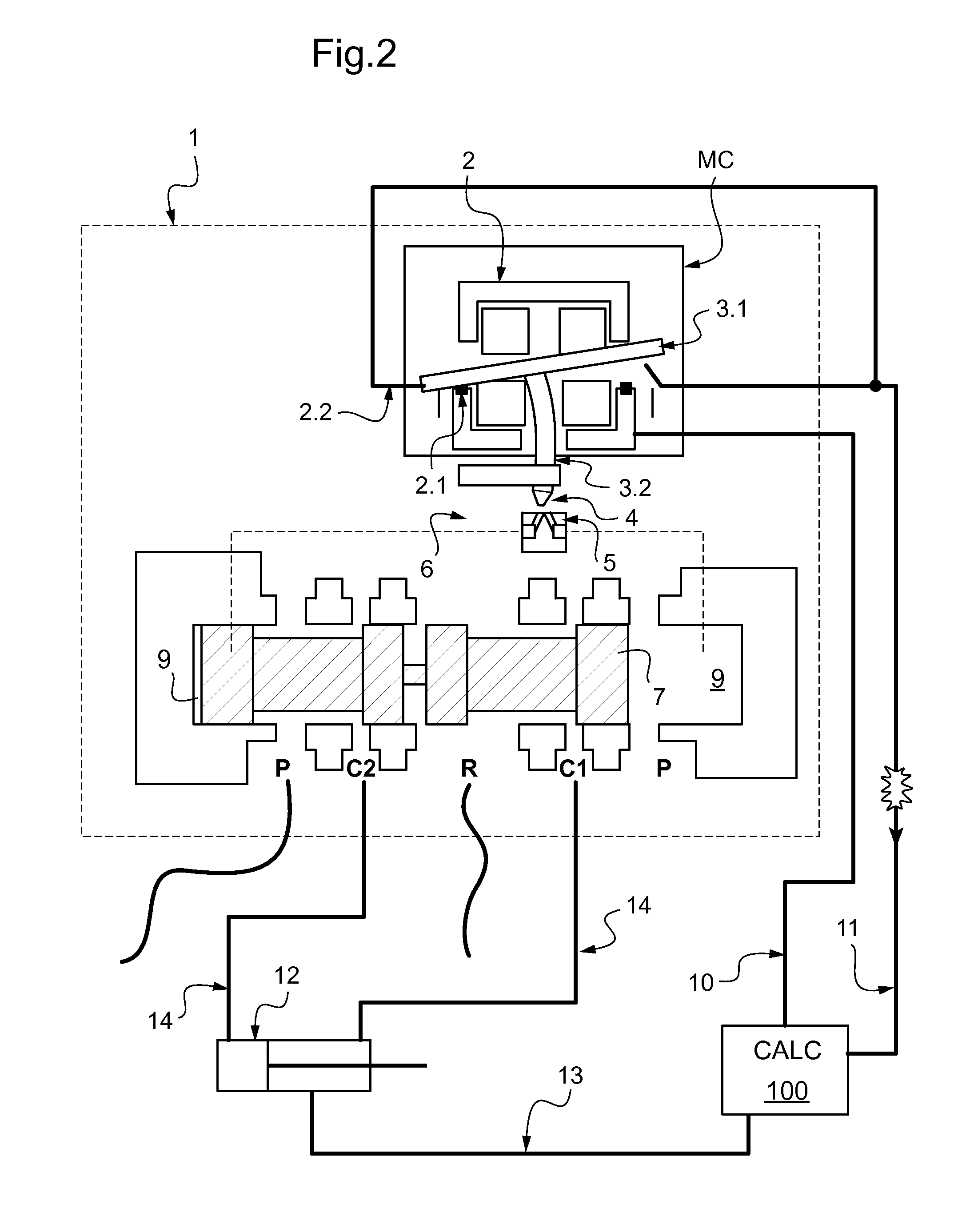
[0031]FIG. 1 is a functional diagram of a servo-valve given overall reference 1. The valve may be incorporated in a control circuit for controlling hydraulic equipment such as an actuator 12 for controlling a flap on an airplane wing. The servo-valve includes a torque motor referenced MC.

[0032]The servo-valve 1 has a pilot stage and a power stage. The pilot stage comprises a torque motor MC that is moved under control of a computer 100 that transmits its instructions to the torque motor MC via an instruction channel 10. The power stage is connected to a hydraulic power supply P, a return port R, and to two outlets C1 and C2. The outlets C1 and C2 feed the two chambers of a double-acting actuator 12 via pipes 14. The computer 100 receives information from the torque motor via an operation-monitoring channel 11 and also information about the position of the actuator via an information channel 13.

[0033]The torque motor MC comprises a stator 2 and a rotor 3. The stator 2 is a cage that ...


PUM


Abstract

A method of detecting failure of a two-stage servo-valve in which the power-controlling movable member is connected to the rotor of a torque motor of a pilot stage by mechanical feedback. A malfunction signal is generated in response to detecting that the rotor of the torque motor has engaged a stop. The invention also provides a servo-valve including means for implementing such a method.

Description

[0001]The present invention relates to a method and a device for detecting failure of a two-stage flow servo-valve in which the movable member for distributing power is connected to the rotor of the torque motor of the pilot stage by mechanical feedback. The invention also provides a servo-valve including such a device.STATE OF THE ART[0002]A conventional servo-valve is constituted by a pilot stage of the oscillating or deflected jet type or of the nozzle type with a flapper controlling a movable power distribution member of the power stage. The function of the power stage is to deliver a pressure or a flow proportional to an instruction delivered to the pilot stage.[0003]In such servo-valves, the relative position of the hydraulic emitter (nozzle or ejector) and of the hydraulic receiver (stationary flapper, deflector, or receiver) of the pilot stage gives rise to pressure differentials that are used for finely moving the movable power distribution member of the power stage of the ...

Claims


Application Information

Patent Timeline
Patent Type & Authority Applications(United States)
IPC IPC(8): F16K37/00
CPCF15B13/0436H02K11/001H02K26/00F15B19/005H02K11/20Y10T137/0318Y10T137/0396Y10T137/2278Y10T137/8158Y10T137/8242Y10T137/8275Y10T137/86598
Inventor OZZELLO, GUYLAIN
Owner SAFRAN AEROSYSTEMS HYDRAULICS
Why Eureka
Try Eureka