
Vehicular pneumatic tire and process of making vehicular pneumatic tire

a technology of pneumatic tires and pneumatic tires, which is applied in the direction of tires, vehicle components, non-skid devices, etc., can solve problems such as unfavorable noise production

Inactive Publication Date: 2002-08-27
CONTINENTAL REIFEN DEUTSCHLAND GMBH
View PDF14 Cites 59 Cited by
  • Summary
  • Abstract
  • Description
  • Claims
  • Application Information

AI Technical Summary

Benefits of technology

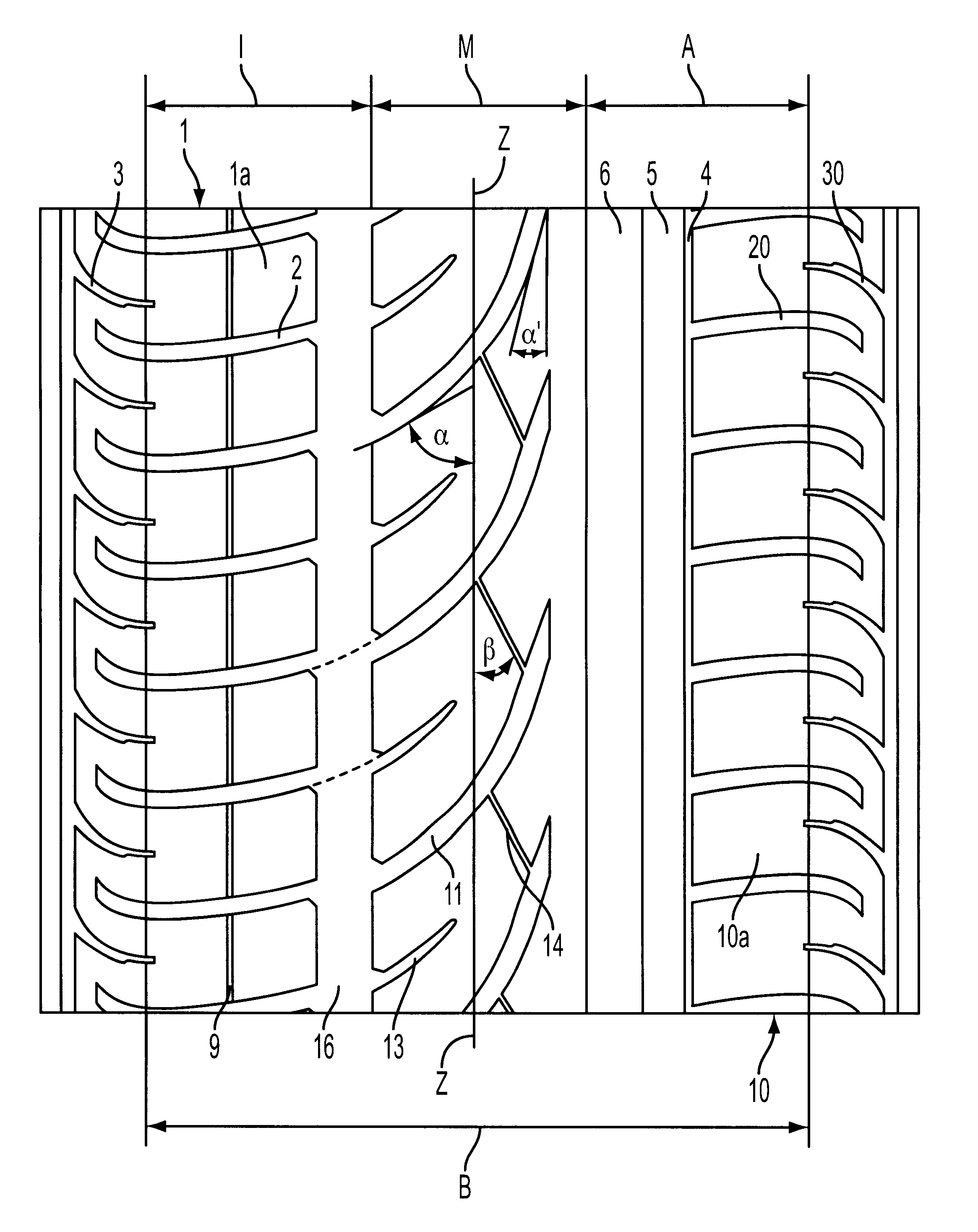
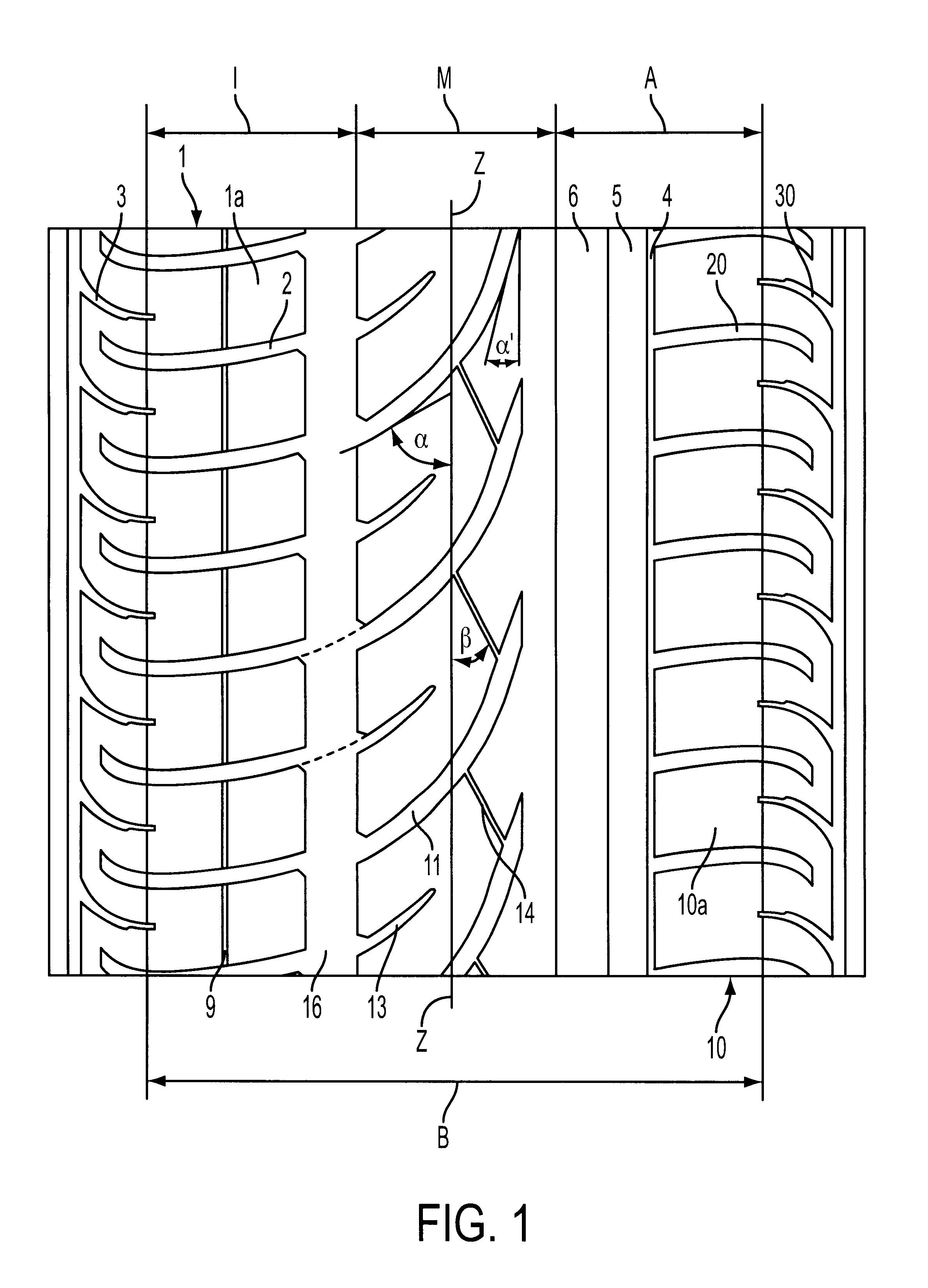
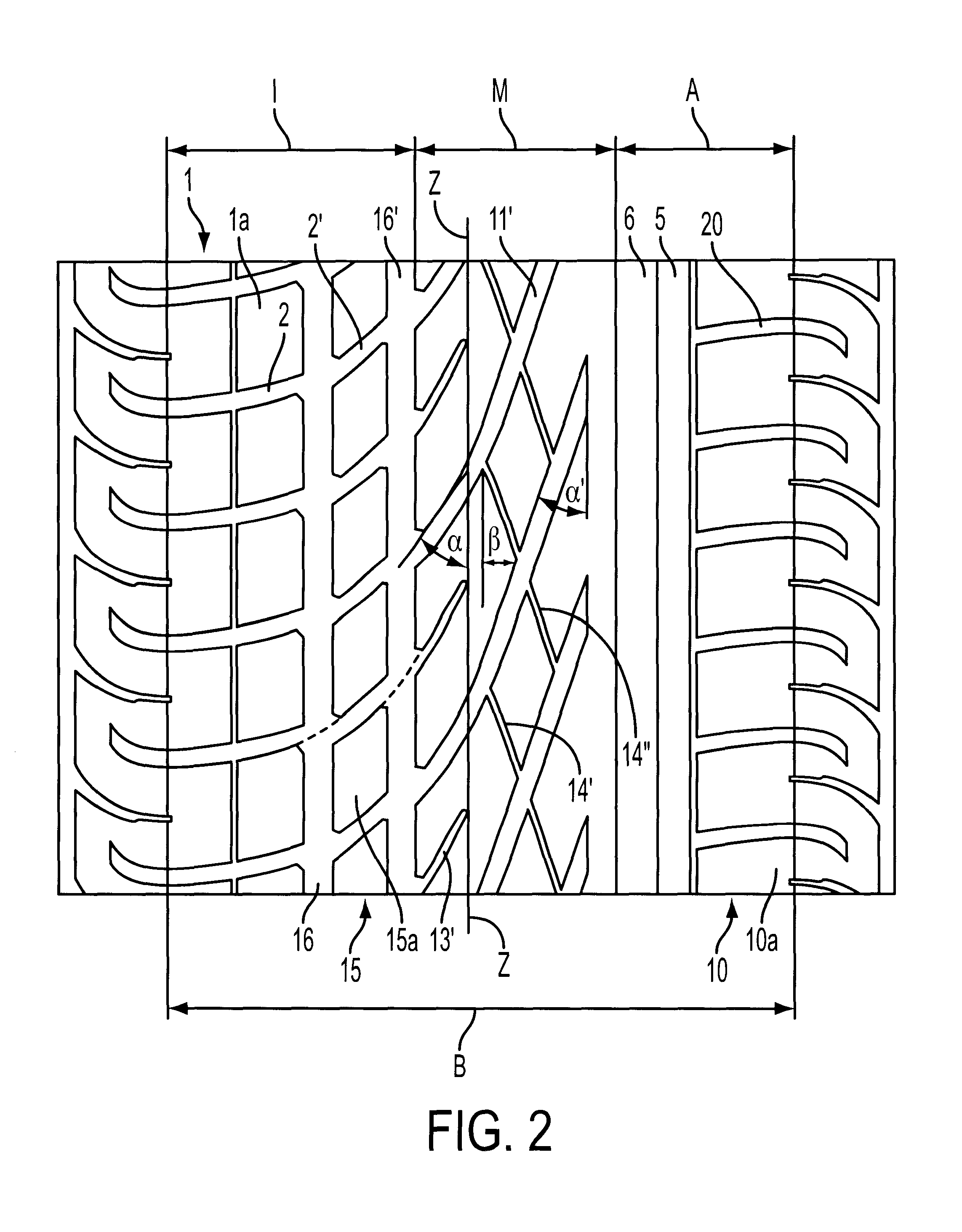
Therefore, tread profiles designed according to the instant invention offer the advantage that, in the center region of the tread, the drainage ability of the tread profile toward the inside region, which is known to be of primary importance, is improved by the grooves at least nearly traversing the center region. Because not all of the transverse grooves have such a continuation from the shoulder block row into the center region, the creation of excessively narrow profile positives in the center region is avoided with the specified acute-angle design of the grooves. This measure is advantageous not only for tread wear but, e.g., also for the rolling noise produced. Specifically, in the center region, abrupt impacts in the inlet and undesired oscillations in the outlet are avoided. Moreover, due to the remaining residual impulses, only frequencies with a half-tone pitch in comparison with the impulses from the shoulder are generated in the tread center region, which results in a mixed frequency that is pleasant to the human ear.
For tires with wide dimensions, it may be advantageous when an additional block row is located between the shoulder block row of the inside region and the center region. This arrangement allows the tread profile to be widened while retaining the desired profile characteristics.

Problems solved by technology

With such a tread profile, drainage capability can be improved, but the rib profile elements running at an acute angle to the tire circumference center line over the majority of the tread width, based on their length, are so narrow that, in tires having such a profile design, uneven wear occurs and, contrary to the assumption expressed in the document, a rather unfavorable noise production would occur.

Method used


Image

  • Vehicular pneumatic tire and process of making vehicular pneumatic tire
  • Vehicular pneumatic tire and process of making vehicular pneumatic tire
  • Vehicular pneumatic tire and process of making vehicular pneumatic tire

Examples


Embodiment Construction

The particulars shown herein are by way of example and for purposes of illustrative discussion of the embodiments of the present invention only and are presented in the cause of providing what is believed to be the most useful and readily understood description of the principles and conceptual aspects of the present invention. In this regard, no attempt is made to show structural details of the present invention in more detail than is necessary for the fundamental understanding of the present invention, the description taken with the drawings making apparent to those skilled in the art how the several forms of the present invention may be embodied in practice.

The embodiments of tread profiles illustrated in FIGS. 1-3 are intended, e.g., for automobile radial tires that can be driven at higher speeds and, in particular, are appropriate as so-called "summer tires." In this regard, the tread profiles formed according to the instant invention are profiles which are asymmetric relative t...


PUM

PropertyMeasurementUnit
Fractionaaaaaaaaaa
Fractionaaaaaaaaaa
Fractionaaaaaaaaaa

Abstract

Vehicular pneumatic tire having an asymmetric tread formed in relation to a circumference of a running surface and process of making vehicular pneumatic tire. The vehicular pneumatic tire includes an outside region that includes an outside shoulder block row and an outside circumferential groove, an inside region that includes an inside shoulder block row and an inside circumferential groove, and a center region that is laterally delimited by the outside circumferential groove and the inside circumferential groove. A plurality of transverse grooves are arranged within the inside shoulder block row, and the plurality of transverse grooves further are arranged to extend into the center region. No more than about one-half of the plurality of transverse grooves are arranged to at least nearly entirely traverse the center region and are oriented to form an angle to a circumferential equator line of no more than approximately 30° over at least one-third of their longitudinal extensions. The process includes forming an outside region to include an outside shoulder block row and an outside circumferential groove, forming an inside region to include an inside shoulder block row and an inside circumferential groove, and laterally delimiting a center region with the outside circumferential groove and the inside circumferential groove. The process further includes arranging a plurality of transverse grooves within the inside shoulder block row and to extend into the center region. No more than one half of the plurality of transverse grooves are arranged to at least nearly entirely traverse the center region and are oriented to form an angle to a circumferential equator line of no more than approximately 30° over at least one-third of their longitudinal extensions.

Description

1. Field of the InventionThe present invention relates to a vehicular pneumatic tire having a tread that is asymmetrically designed relative to a circumference of the running surface, i.e., the tread includes an outside and an inside region, which are related to the vehicle to which the tire is to be mounted, and each region has a shoulder block row. The tread also includes a center region that is laterally delimited by circumferential grooves belonging to the outside or inside region. Further, transverse grooves in the shoulder block row of the inside region are arranged to extend into the center region.2. Discussion of Background InformationDifferent embodiments of tires having asymmetrical tread profiles are known from prior art. Asymmetrical tread profiles are fundamentally those that, relative to the vehicle to which the tire will be mounted, have an inside region and an outside region and the profile structures of these regions fundamentally differ from one another. Indeed, wi...

Claims


Application Information

Patent Timeline
IPC IPC(8): B60C19/00B60C11/03B60C11/13B60C11/04
CPCB60C19/001B60C11/0304B60C2011/0388B60C2011/0383B60C2011/0374
Inventor BAUMHOFER, JOHANNES-JOSEFWIES, BURKHARDJANSEN, MICHAEL
Owner CONTINENTAL REIFEN DEUTSCHLAND GMBH
Learn More