
Pan frame structure of seat cushion of a vehicle seat

a seat cushion and pan frame technology, applied in the field of pan frame structure of seat cushion, can solve the problems of affecting the service life of the seat cushion,

Inactive Publication Date: 2002-08-27
TACHI S CO LTD
View PDF7 Cites 10 Cited by
  • Summary
  • Abstract
  • Description
  • Claims
  • Application Information

AI Technical Summary

Benefits of technology

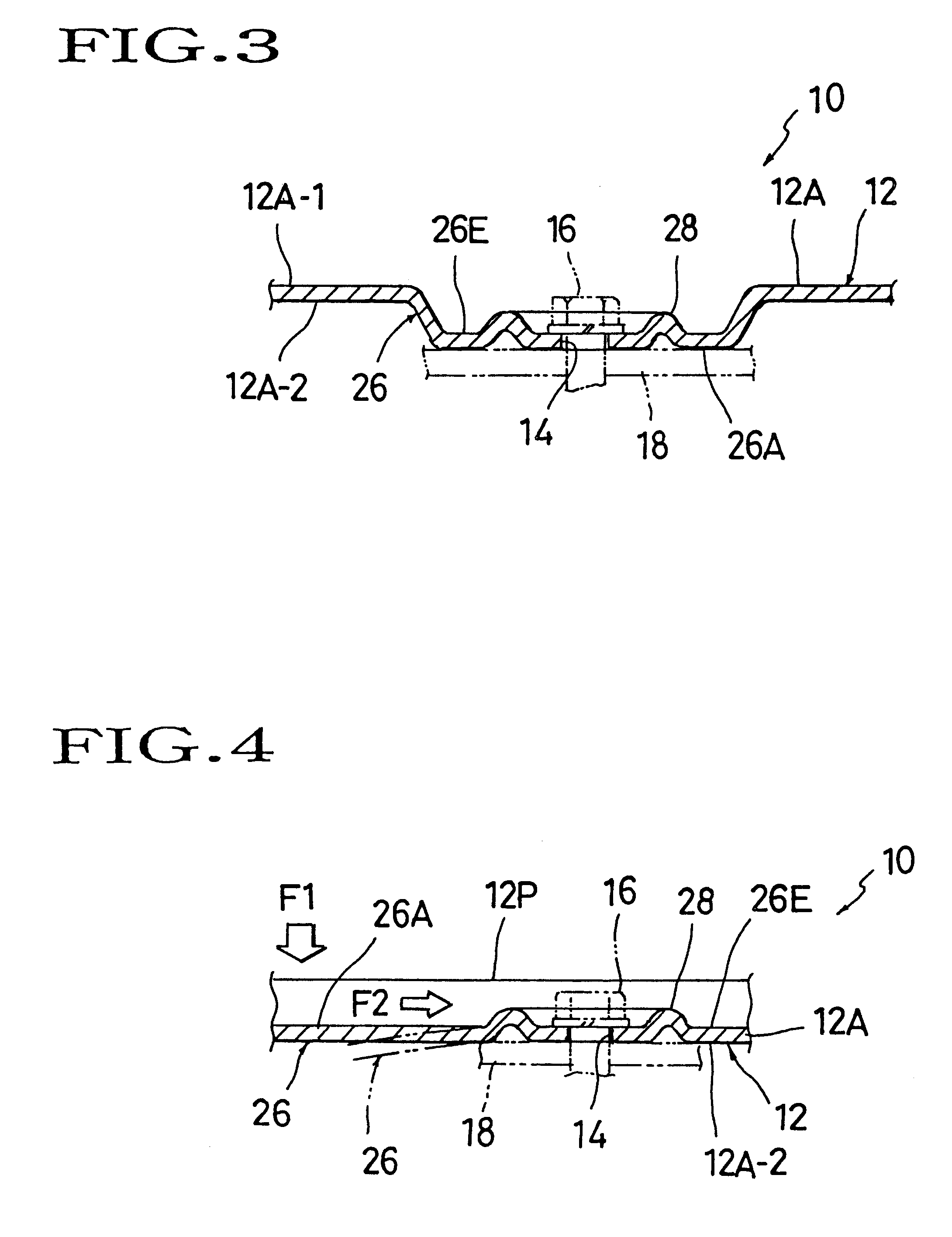
Accordingly, the provision of such auxiliary reinforcing pattern is effective in surrounding and isolating the securing areas from other areas of the pan frame including the primary reinforcing pattern, whereupon a load applied to the pan frame is blocked by the auxiliary reinforcing pattern against transmission to the securing areas and will be changed thereby in direction so that it is smoothly escaped to the outside of pan frame.

Problems solved by technology

Over a lengthy period of its use with an automotive seat, the pan frame receives a continued load and vibrations from the occupant and automobile for a long mileage of driving, resulting in a considerable wear or metal fatigue in the frame.
As a result, it is possible that the frame will be deformed, causing an unstable poor seating touch of the seat cushion as a whole, and further, the less stiff areas of the frame, i.e. the securing holes of frame through which the securing bolts pass, will become lower in strength, and, in the worst case, the peripheral regions of each securing hole might be broken and cracked.
However, such provision of reinforcing members has led to increase of fitting parts and intricate structure of the frame, while the thickened frame has encountered the increased size and weight of frame itself.
Those hitherto breakthroughs are found hardly acceptable cost-wise and in assembly of the frame.

Method used


Image

  • Pan frame structure of seat cushion of a vehicle seat
  • Pan frame structure of seat cushion of a vehicle seat
  • Pan frame structure of seat cushion of a vehicle seat

Examples


Embodiment Construction

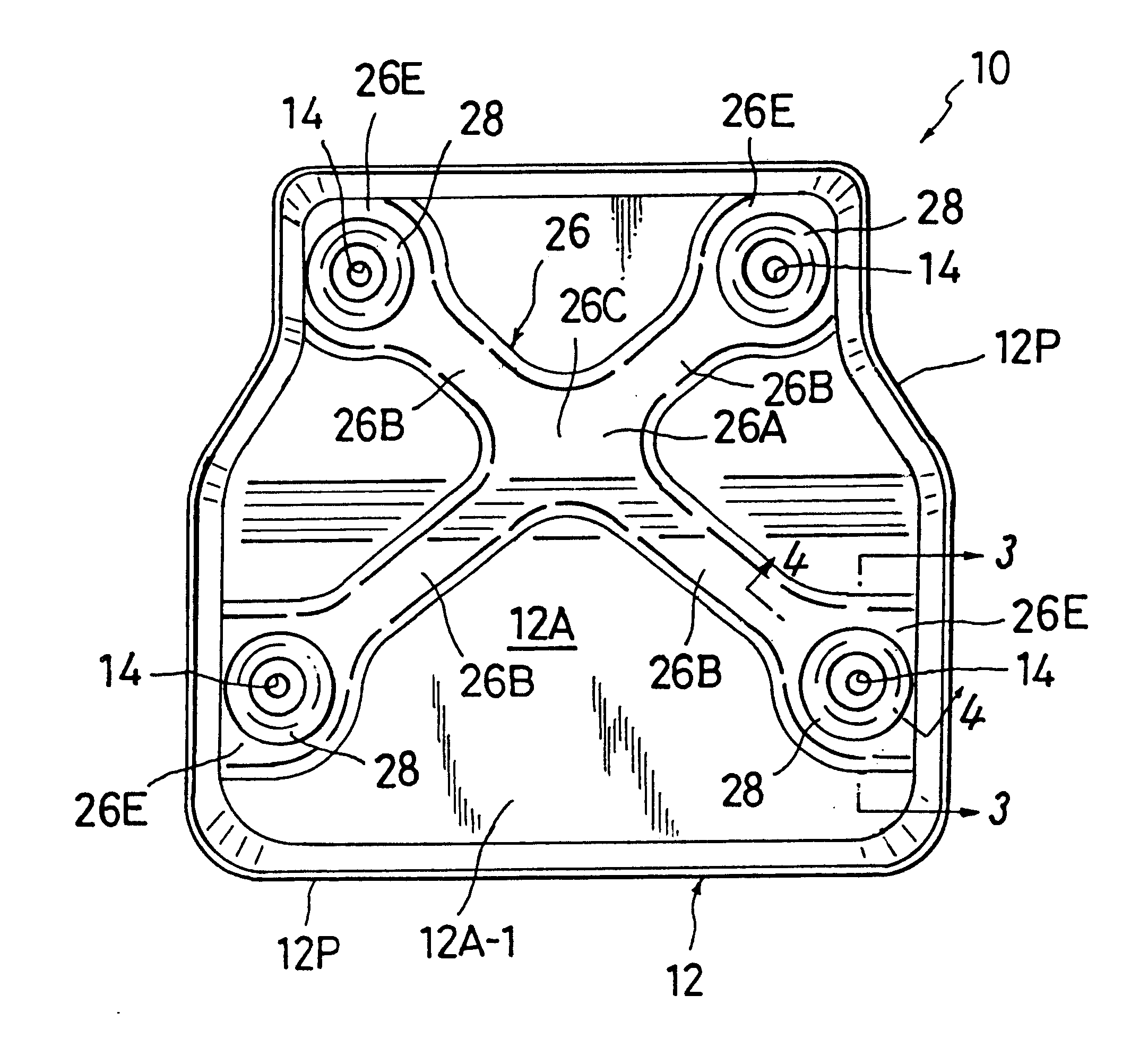
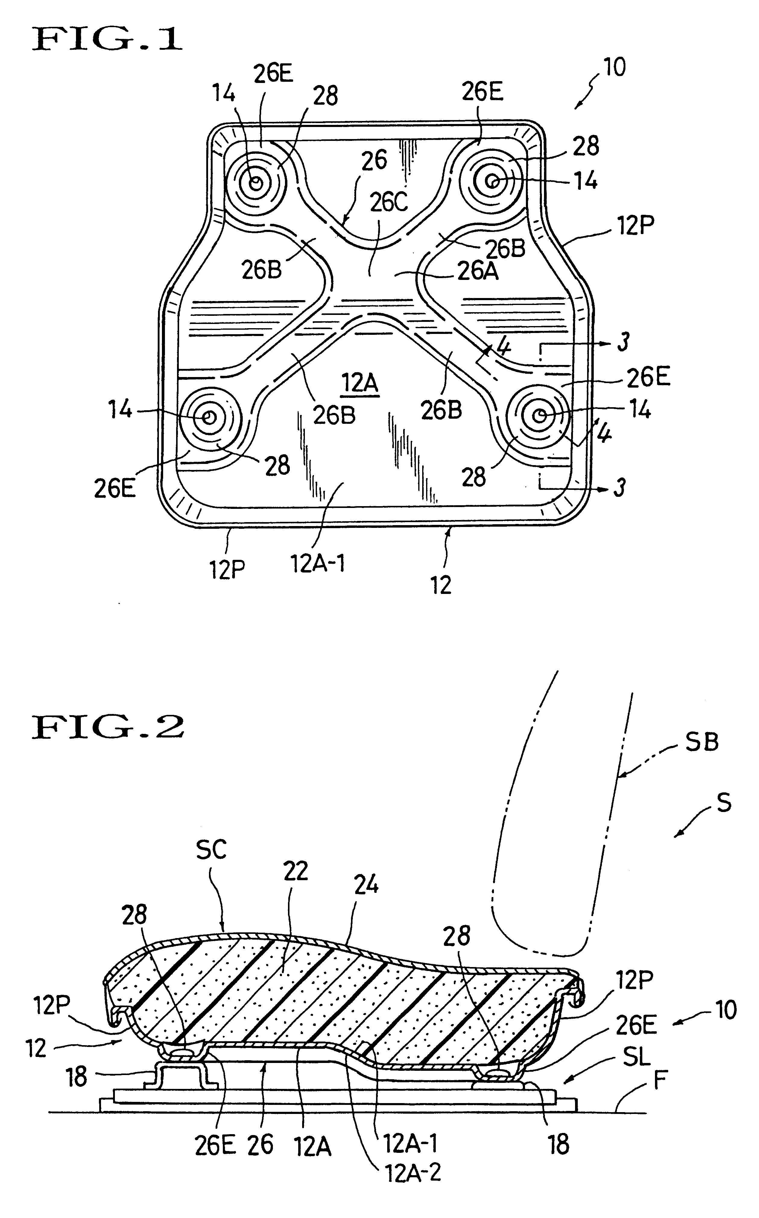
In the present invention, a whole structure of seat-cushion pan frame is best illustrated in the front view of FIG. 1, as generally designated by (10). The seat-cushion pan frame structure is to be incorporated in a seat cushion (SC) which forms a part of a vehicle or automotive seat (S ), as indicated in FIG. 2 for example. The seat-cushion frame structure (10) uses a pan-type frame (12) discussed earlier, as a seat cushion frame. The illustrated mode of pan frame (12) is of a generally rectangular shape in the plan as viewed from FIG. 1, having four corners. Formed respectively adjacent to the four corners of frame (12) are each securing hole or through-hole (14) adapted for allowing a securing bolt (see (16) in FIG. 3) to be inserted thereth rough. Hence, as can be seen from FIGS. 2 and 3, the pan frame (12) may be fixedly connected to the floor side (F) by those four bolts (16) being threadedly fastened to predetermined threaded holes or nut members which are for example formed ...


PUM


Abstract

A structure of the so-called "pan frame" of seat cushion for use with a vehicle seat, which includes a primary reinforcing pattern press formed therein. The primary reinforcing pattern has a flat bottom region defined on its top and protrudes from the bottom wall of the seat-cushion pan frame. The primary reinforcing pattern further communicates with the securing areas where the frame is to be secured to a floor side of the vehicle. Hence, most of a load applied to the pan frame is dispersed via such pattern toward the securing areas, while being absorbed thereby. An auxiliary reinforcing pattern is press formed in the primary reinforcing pattern such as to surround each of the securing areas, thereby blocking further transmission of the load thereto. The primary reinforcing pattern may be of a generally X-shaped channel configuration which communicates its four channel sections with the securing areas, whereas the auxiliary reinforcing pattern be of an annularly protruded configuration that surrounds each of the securing areas.

Description

BACKGROUND OF INVENTION1. Field of the InventionThe present invention relates to a so-called "pan frame" of seat cushion for use with a vehicle seat, and in particular, to the structure of seat-cushion pan frame which is formed by a press working from a rigid plate material, such as a steel sheet.2. Description of Prior ArtA typical seat cushion of a vehicle or automotive seat is generally composed of an elastic padding and a covering material affixed thereon, with a seat cushion frame provided for supportive receipt of the elastic padding. In most cases, the covering material is attached over a unit of the padding and seat cushion frame in an integral manner, thus presenting one integrated appearance of seat cushion.Among various kinds of frameworks for the seat cushion, known is the so-called "pan frame" which is one unitary frame formed in a pan-like configuration by press working from a rigid material or a seat steal for instance. This seat-cushion pan frame is normally fixed on...

Claims


Application Information

Patent Timeline
IPC IPC(8): B60N2/005B60N2/015B60N2/68A47C7/02B60N2/90
CPCB60N2/015B60N2/686
Inventor KIMURA, TOSHIMITZUMURAISHI, MASAMI
Owner TACHI S CO LTD
Learn More