Snare drum mechanism

US6441287B1Inactive Publication Date: 2002-08-27STEVE P CROUCH +2

Image

  • Snare drum mechanism
  • Snare drum mechanism
  • Snare drum mechanism

Examples


Embodiment Construction

The following detailed description illustrates the invention by way of example and not by way of limitation. This description will clearly enable one skilled in the art to make and use the invention, and describes several embodiments, adaptations, variations, alternatives and uses of the invention, including what we presently believe is the best mode of carrying out the invention. As various changes could be made in the above constructions without departing from the scope of the invention, it is intended that all matter contained in the above description or shown in the accompanying drawings shall be interpreted as illustrative and not in a limiting sense.

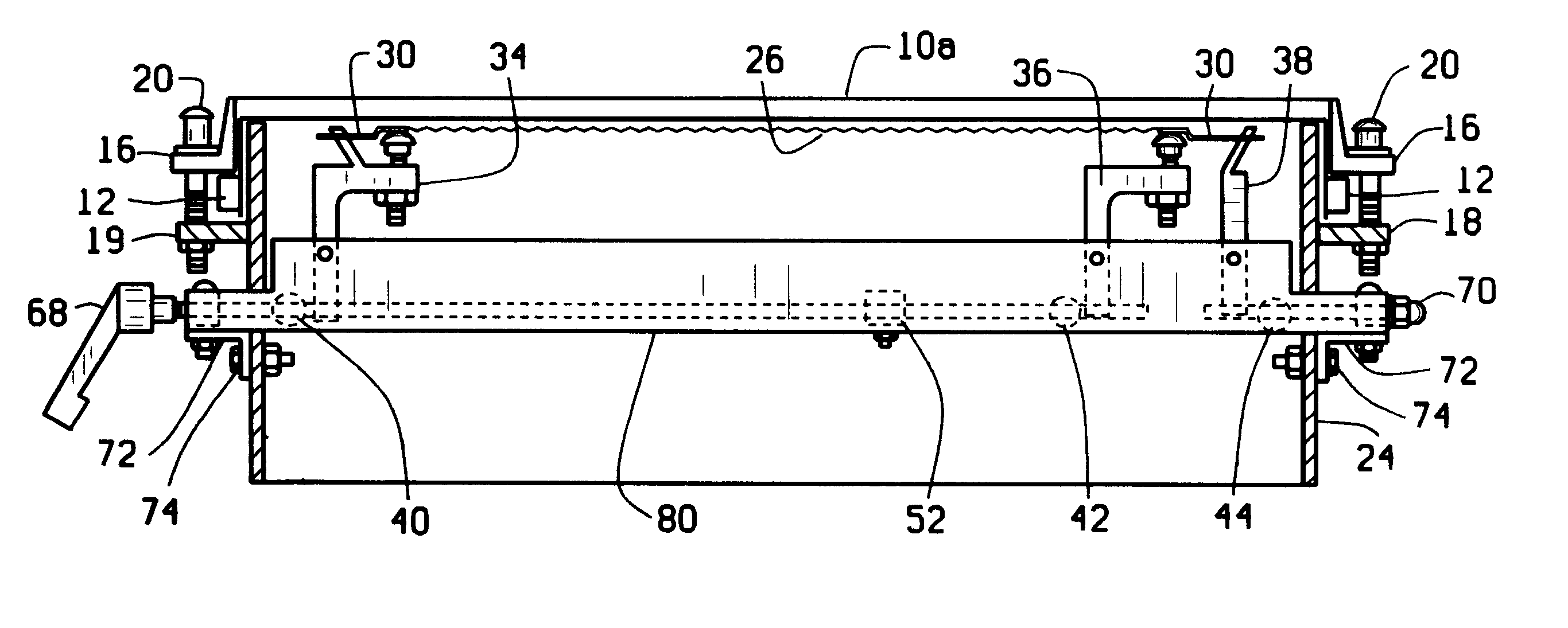
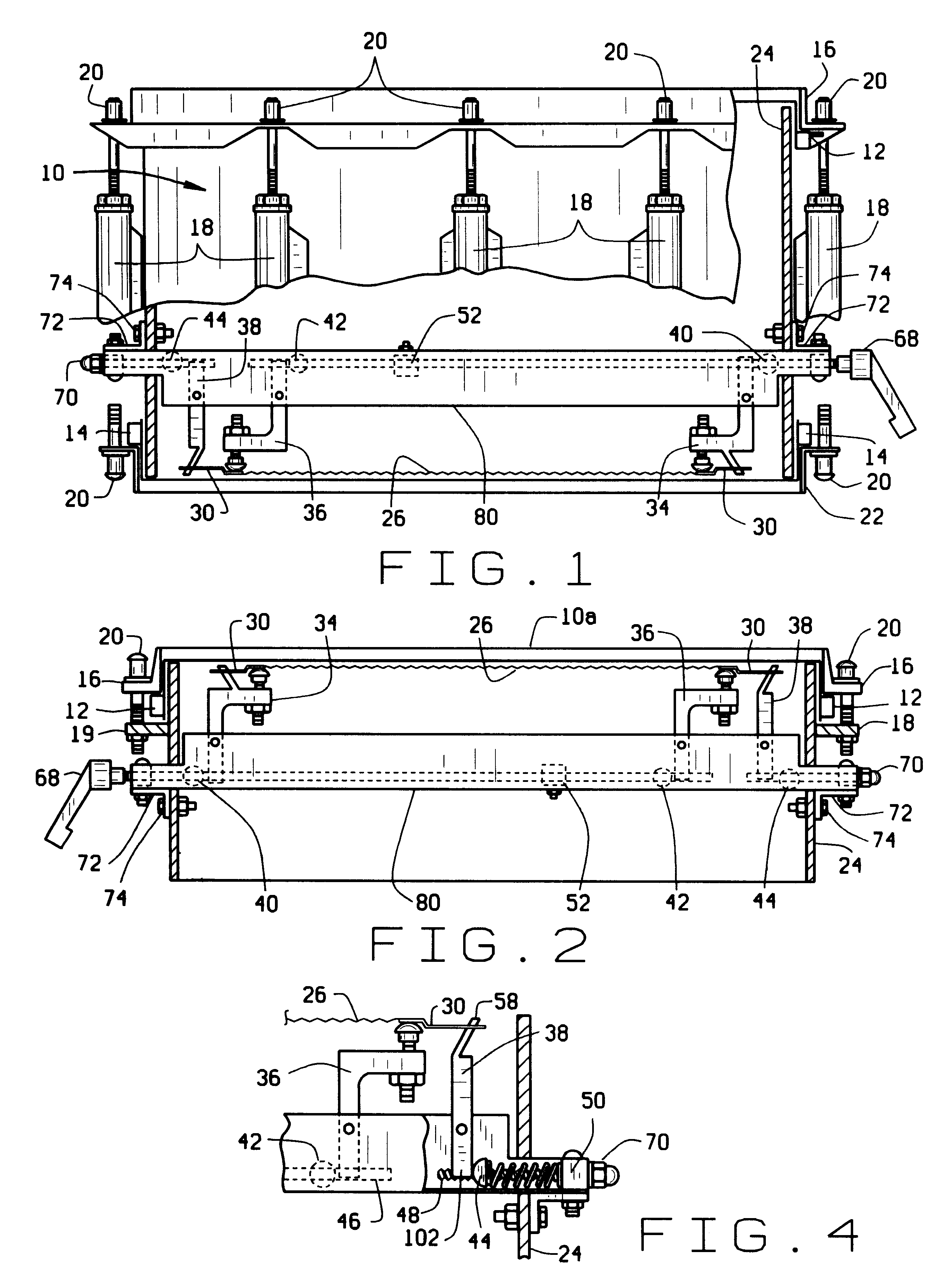
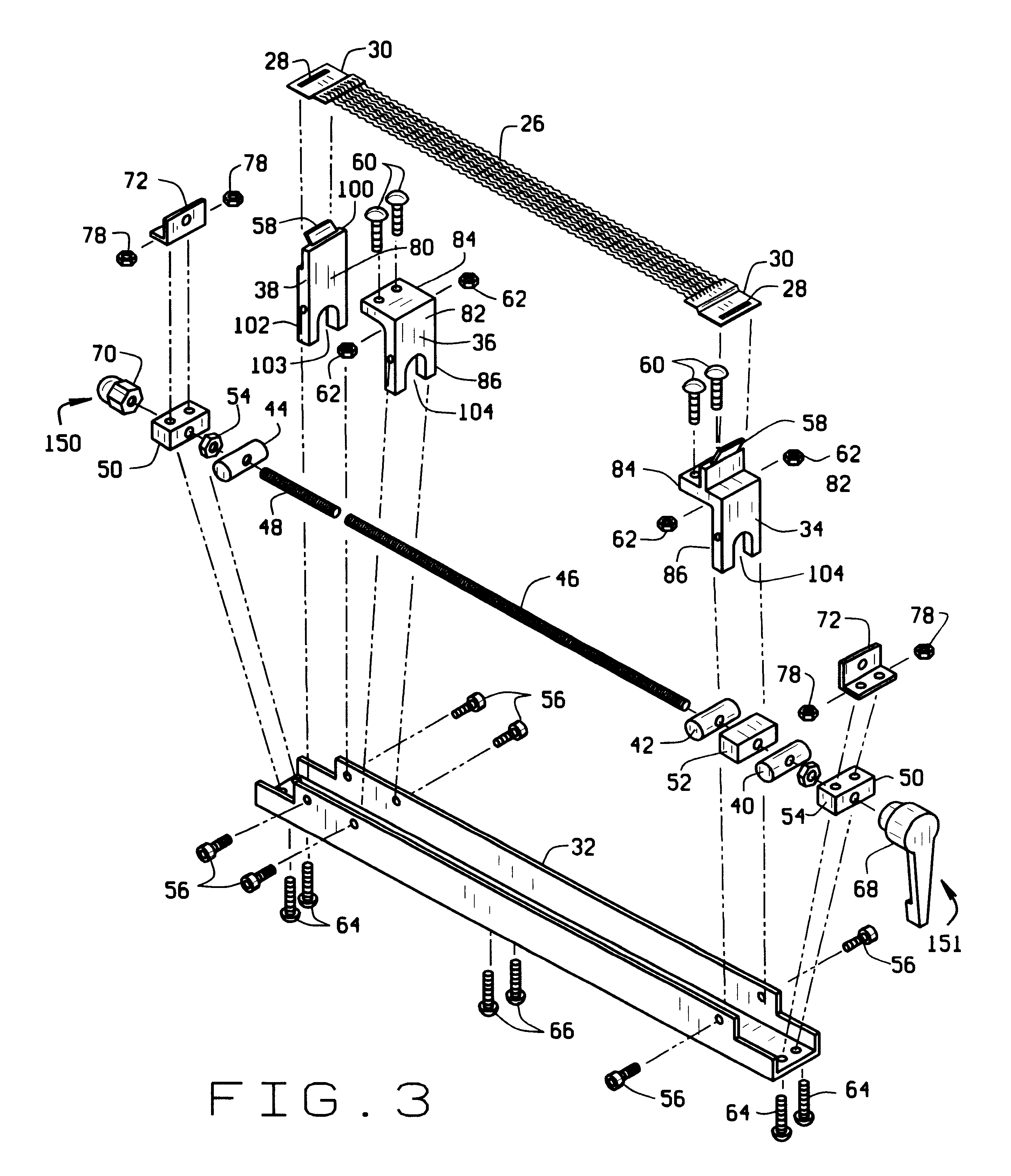
Referring now to FIG. 1, reference numeral 10 indicates a snare drum employing one illustrative embodiment of snare mechanism 80 of the present invention. As will be appreciated by those skilled in the art, the drum 10 is conventional, and includes a shell 24, a top hoop 16, a bottom hoop 22, a top drum head 12, and a bottom drum h...


PUM


Abstract

A snare drum assembly is provided which enables the snare drum element to be positioned internally of a drum. In the preferred embodiment, the snare mechanism acts against the top drum head of a drum, and permits the drum manufacturer to eliminate the lower drum head and related structure, greatly simplifying drum construction and cost.

Description

BACKGROUND OF THE INVENTIONThis invention relates to snare drums, and in particular, to a device for positioning snare mechanisms internally of a drum which permits adjustment of both the tension on and the position of a snare assembly with respect to a drum head through a single adjustment device positioned externally of the drum.Snare drums are used frequently in marching bands. These drums produce a unique sound due to the snare mechanism. The snares commonly are located externally of the drum, generally being positioned on the bottom of the drum against the lower drum head. Even when the snare mechanism is positioned internally of the drum, however, the conventional construction employed for these drums has left unsolved a number of problems associated with their construction.For younger and older musicians in a marching band, for example, the snare drum can become heavy, especially after being carried over a long parade route. The largest part of the weight comes from the top a...

Claims


Application Information

Patent Timeline
27 Aug 2002
Publication
US6441287B1
IPC
G10D13/02; G10D13/00
CPC
G10D13/025; G10D13/02; G10D13/18
Inventors
CROUCH, STEVE P.; SCHAFER, MARK W.