Remote signaling device for a rolling code security system

a security system and remote signaling technology, applied in the field of wireless security systems, can solve problems such as security risks in conventional security systems

Inactive Publication Date: 2002-08-27
TSUI PHILIP Y W
View PDF9 Cites 78 Cited by
  • Summary
  • Abstract
  • Description
  • Claims
  • Application Information

AI Technical Summary

Problems solved by technology

Such conventional security systems create security risks.
Further, a single, fixed identification code may be generated by a non-system source and incorrectly recognized as a system signal.

Method used


Image

  • Remote signaling device for a rolling code security system
  • Remote signaling device for a rolling code security system
  • Remote signaling device for a rolling code security system

Examples


Embodiment Construction

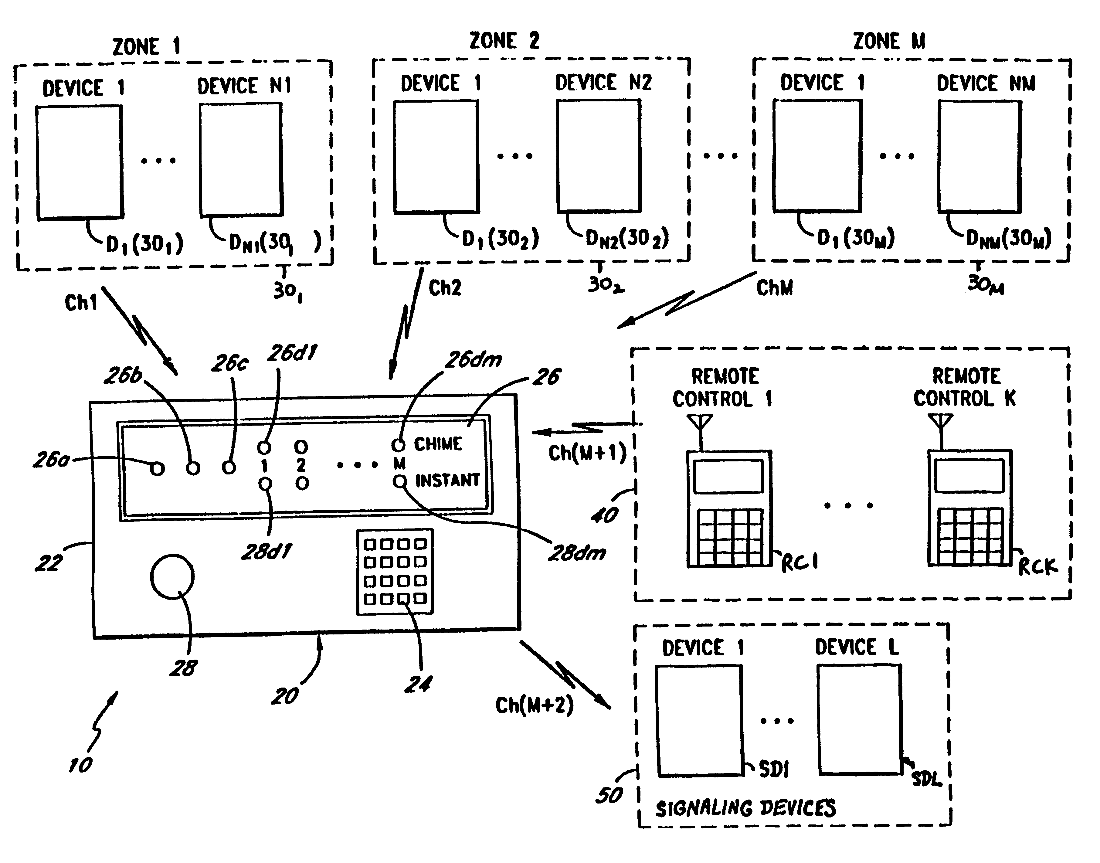
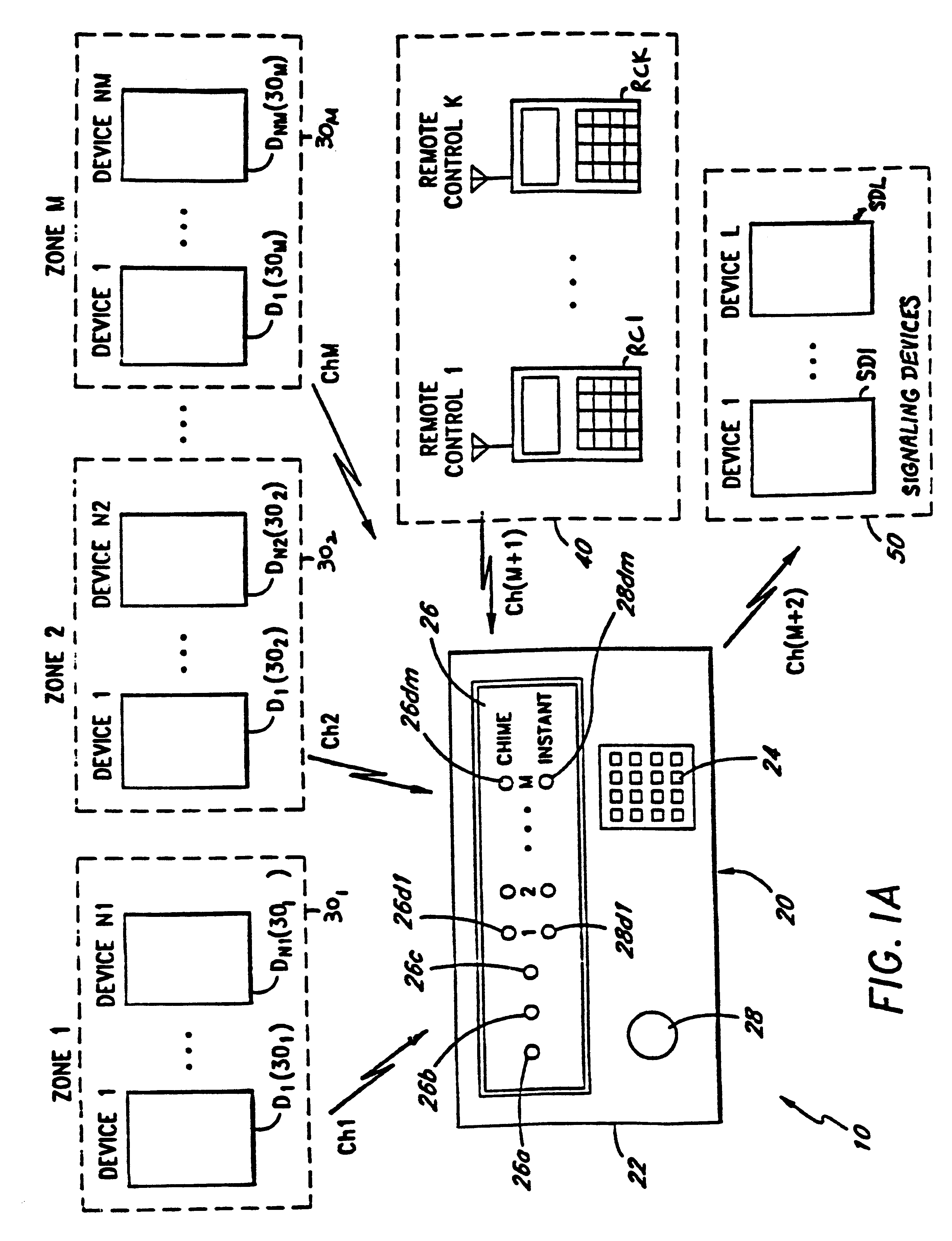
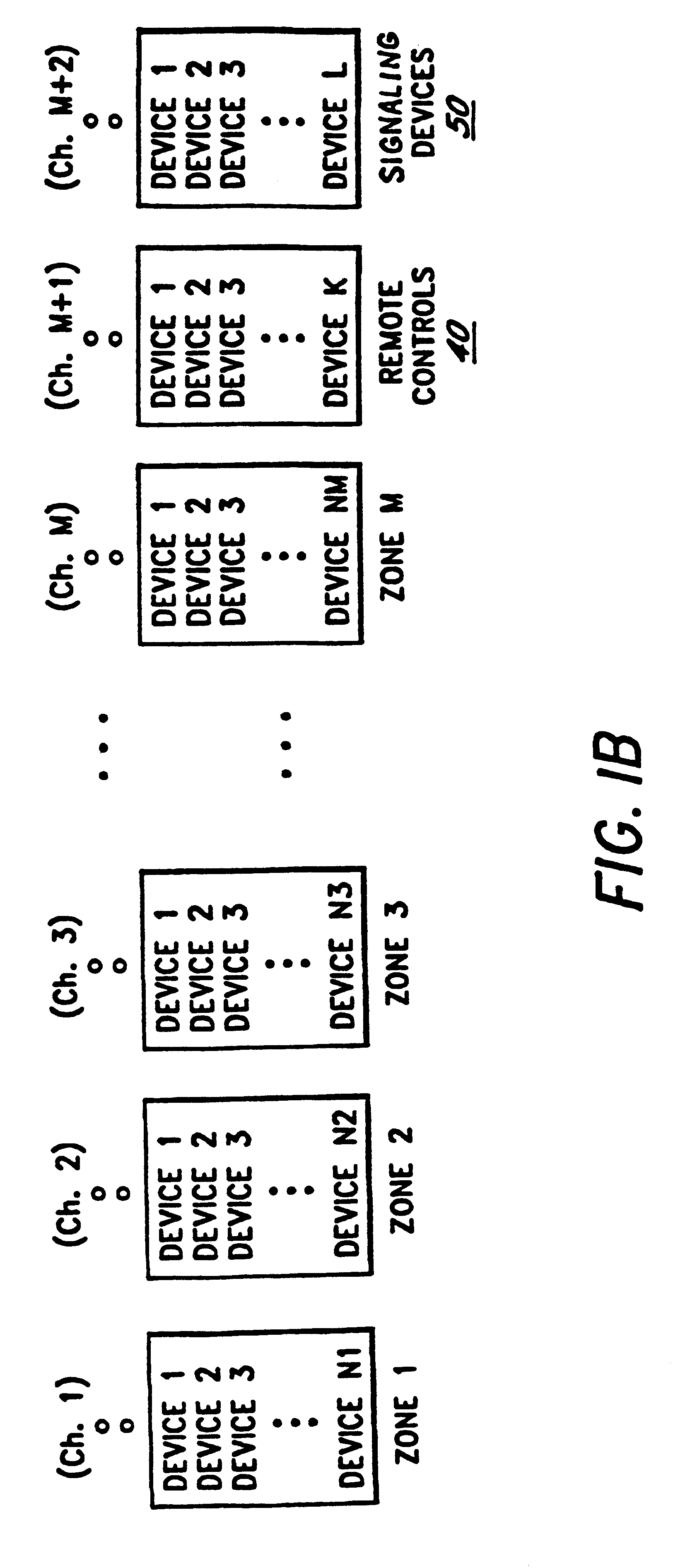
FIG. 1A is a block diagram illustrating one embodiment of the security system of the present invention. The security system 10 comprises a security console 20, a plurality of sets of peripheral devices D1(30.sub.1)-DN1(30.sub.1), D1(30.sub.2)-DN2(30.sub.2), . . . , D1(30.sub.M)-DN.sub.M (30.sub.M), each of which is allocated to a zone 30.sub.1, 30.sub.2, . . . , 30.sub.M respectively, a plurality of remote controllers RC1, . . . RCK (collectively referred to as remote controllers 40), and a plurality of signaling devices SD1, . . . , SDL (collectively referred to as signaling devices 50). Examples of signaling devices 50 include bells, sirens, strobe lights, and telephone auto dialers.

In one embodiment, the number of peripheral devices D1(30.sub.1)-DN1(30.sub.1), D1(30.sub.2)-DN2(30.sub.2), . . . , D1(30.sub.M)-DNM(30.sub.M) are equal, i.e., N1=N2=NM. However, in alternate embodiments, any desired number of peripheral devices may be assigned to a particular zone 30.sub.1, 30.sub.2, ...


PUM


Abstract

A signaling device that receives coded signals from a transmitter. The signaling device includes a first circuit that receives a from the transmitter. The first code includes a first identification code and a first variable code. The signaling device further includes a memory that stores a second code. The second code includes a second identification code and a second variable code. The signaling device further includes a second circuit coupled to the first circuit and the memory. The second circuit generates an output signal if the first code matches the second code. The signaling device further includes an annunciator circuit coupled to the second circuit. The annunciator circuit provides a perceivable indicator if the second circuit generates the output signal.

Description

1. Field of the InventionThis invention is directed in general to security systems and in particular, to a wireless security system in which a signaling device, which operates with a transmitter, is capable of receiving and verifying coded signals from the transmitter. The transmitter transmits the coded signals using a different data frame pattern during each transmission.2. Prior ArtTransmitter-receiver controller systems are widely used for remote control and / or actuation of devices or appliances such as garage door openers, gate openers, and security systems. For example, most conventional security systems use a transmitter-receiver combination to monitor selected areas. In such conventional security systems, all the peripheral devices such as sensors, and the control unit operate using the same identification code, so that only those devices belonging to a particular installed security system on the premises can operate with each other. Other devices which operate using a diffe...

Claims


Application Information

Patent Timeline
Patent Type & Authority Patents(United States)
IPC IPC(8): G06F19/00G08B1/00H04B1/00E05F15/20G08C19/00G08C19/12
CPCG08C17/02E05F15/77G08C2201/62
Inventor TSUI, PHILIP Y. W.
Owner TSUI PHILIP Y W
Why Eureka
Try Eureka