

Liquid crystal display device and method for fabricating the same
a technology of liquid crystal display and liquid crystal, which is applied in static indicating devices, instruments, non-linear optics, etc., can solve the problems of significant reduction of display quality, lack of concrete methods for fabricating such structures, and difficulty in high-precision control of film thickness
Inactive Publication Date: 2002-09-03
SHARP KK
View PDF9 Cites 22 Cited by
- Summary
- Abstract
- Description
- Claims
- Application Information
AI Technical Summary
Problems solved by technology
As a result, the variation in the axial position among the pixels is observed as a difference in brightness among the pixels, thereby significantly reducing the display quality.
However, the publication does not disclose any concrete method for fabricating such a structure.
When a film is formed using the spin coat method, however, it is difficult to control the thickness of the film with high precision.
Moreover, when a multilayer film is formed using the spin coat method, if a layer formed by a first spin coat step is uneven, a layer formed by a subsequent spin coat step is affected by the unevenness of the underlying layer.
This further makes it difficult to control the thickness of the film with high precision.
In addition, several repetition of the photolithography step (including resist application, light exposure, and development) increases the possibility of an occurrence of a factor which can reduce the yield, such as positional displacement and attachment of foreign matters.
For the above reasons, in the conventional fabrication method, it is difficult to simplify the steps and suppress the production cost.
In the conventional method, a number of steps are required to form concave portions on a color filter layer substrate, thereby reducing the yield.
Moreover, since colored layers constituting color filter layers are formed by the spin coat method, the thickness of the layers is not likely to be uniform, d
Method used
View moreImage
Smart ImageViewing Examples


Examples
 PUM
 Abstract
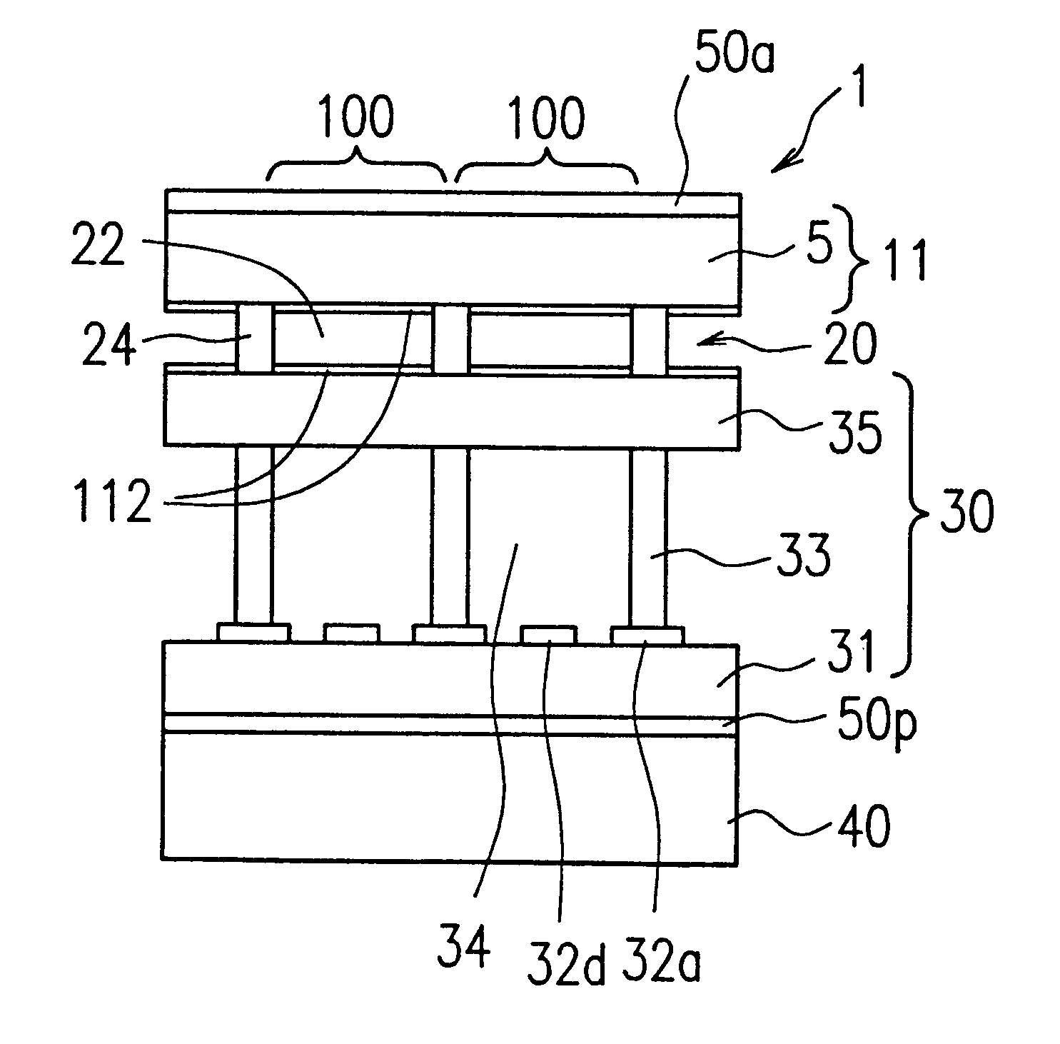
The liquid crystal display device of this invention includes a first substrate, a second substrate opposing the first substrate, and a liquid crystal layer sandwiched between the first and the second substrates, wherein the liquid crystal layer includes a polymer region and a liquid crystal domain surrounded by the polymer region in which liquid crystal molecules are oriented in an axial symmetrical manner, the first substrate includes a dry film having a concave portion on a surface facing the liquid crystal layer, and a symmetric axis in the liquid crystal domain substantially extends through the concave portion and is substantially perpendicular to the first substrate.
Description
1. Field of the InventionThe present invention relates to a liquid crystal display device (hereinafter, ref erred to as an LCD device) having wide viewing angle display characteristics, and a method for fabricating the same.2. Description of the Related ArtJapanese Laid-Open Publication Nos. 6-301015 and 7-120728 disclose a technique of providing wide viewing angle characteristics for an LCD device. Such a technique includes steps of: dividing a liquid crystal layer into liquid crystal domains by surrounding regions thereof corresponding to pixels by a polymer wall; and aligning liquid crystal molecules in the respective liquid crystal domains in an axial symmetrical manner. Such a technique is called an axial symmetrically aligned microcell (ASM) technique. Using the ASM technique, an LCD device having a reduced change in contrast when the angle at which an observer views the LCD device changes in any direction (i.e., having wide viewing angle characteristics) is obtained.In such a...
Claims
Login to View More Application Information
Patent Timeline
 IPC IPC(8): G02F1/13G02F1/1333G02F1/1337
CPCG02F1/133377
InventorHORIE, WATARUNAGAYASU, TAKAYOSHIFUJII, TOSHIO
OwnerSHARP KK