Removable gear drive for mechanical jack

Inactive Publication Date: 2002-09-10
CEQUENT PERFORMANCE PROD
View PDF13 Cites 56 Cited by
  • Summary
  • Abstract
  • Description
  • Claims
  • Application Information

AI Technical Summary

Benefits of technology

The present invention overcomes the disadvantages of the prior known jack assemblies by providing a gear dri

Problems solved by technology

The cooperation of the components within the jack tube creates difficulty in assembly particularly for components whic

Method used


Image

  • Removable gear drive for mechanical jack
  • Removable gear drive for mechanical jack
  • Removable gear drive for mechanical jack

Examples


Embodiment Construction

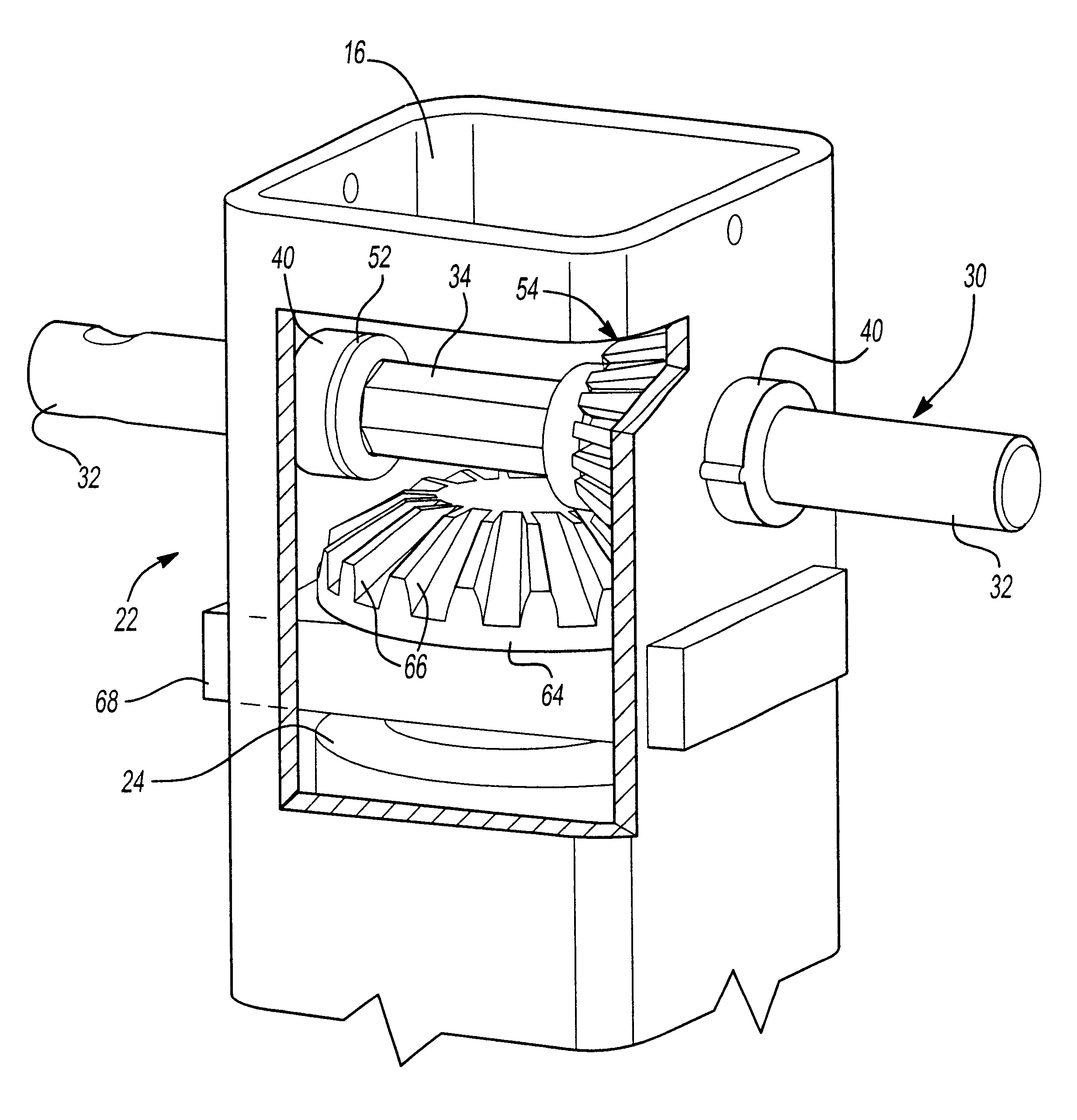
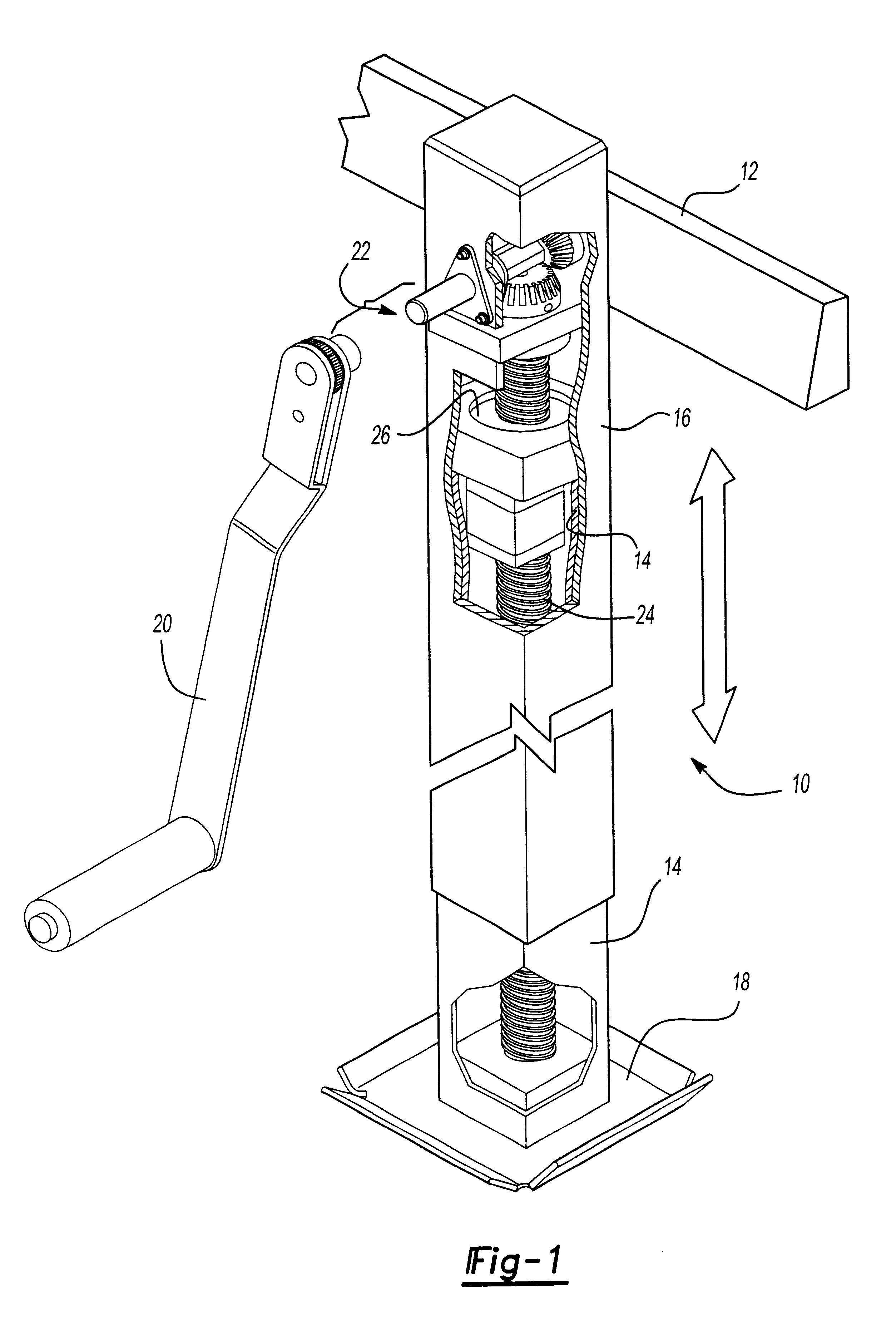
Referring first to FIG. 1, there is shown a jack assembly 10 selectively extendable and contractible to raise and lower a structure 12 such as a portion of a recreational vehicle. The recreational vehicle may need to be raised or lowered for leveling or to facilitate attachment to a towing vehicle. The jack assembly 10 generally includes a lower jack tube 14 telescopically received within an upper jack tube 16. A ground engaging footpad 18 may be attached to the lower tube 14 while the upper tube 16 is secured to the structure 12 in a well known manner. In accordance with the present invention, an external crank 20 is used to operate the jack 10 to raise and lower the structure 12 as desired.

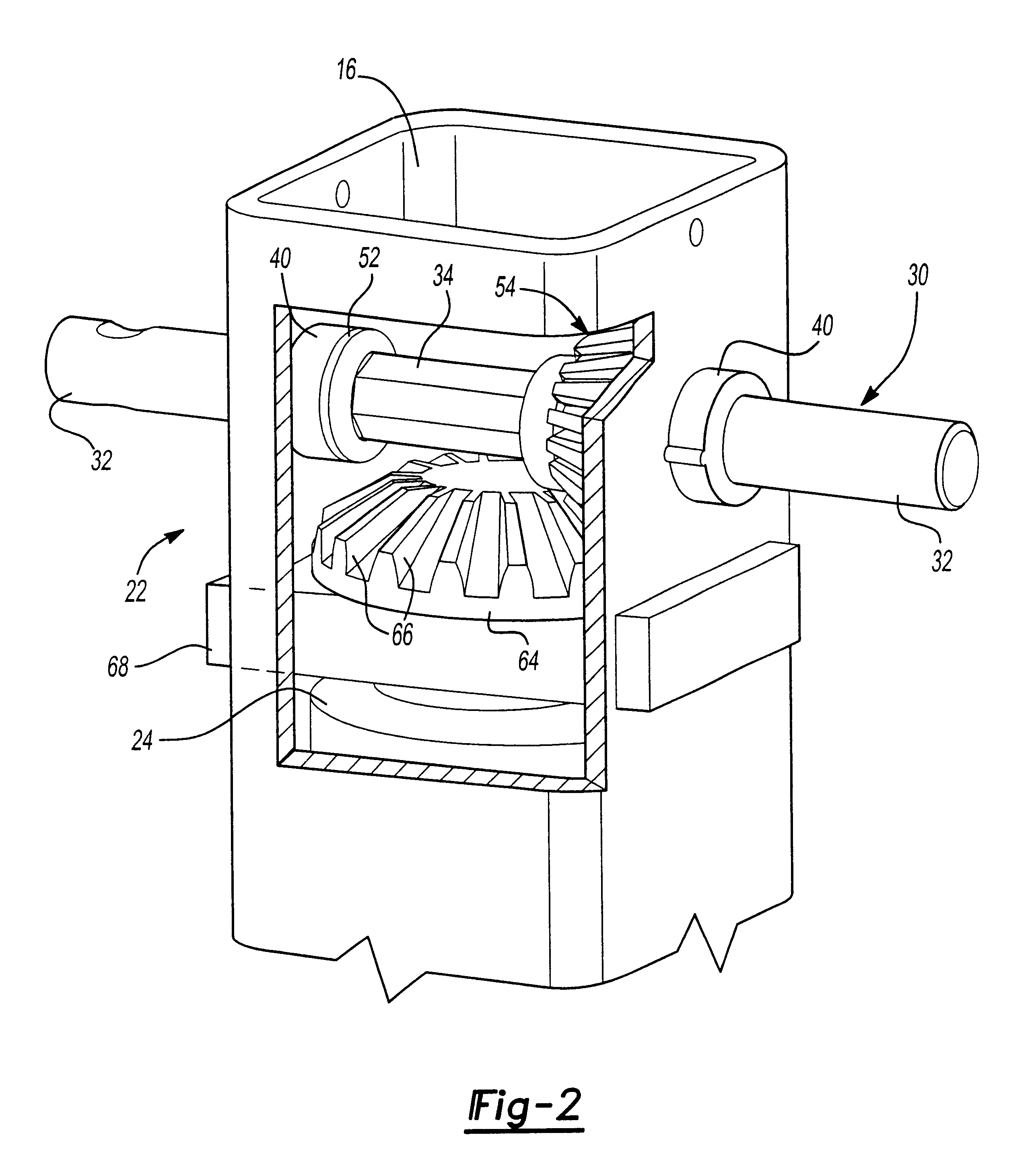
The crank 20 is operatively connected to a gear drive assembly 22 embodying the present invention which is drivably connected to a jack screw 24 extending axially through the tubes 14,16. The jack screw 24 extends through and is threadably connected to a screw nut 26 secured to the lower tube 14...


PUM


Abstract

A jack assembly for raising and lowering an object such as a trailer. The jack includes telescoping jack tubes which are expanded and contracted through operation of an axial screw. The screw is drivably connected to a gear drive mounted in an upper end of the jack. A crankshaft is supported within the upper end of the jack tube by a pair of end bushings and includes a hexagonal intermediate portion. A first pinion gear having a hexagonal throughbore is drivably mounted to the intermediate portion of the crankshaft. The first gear is in driving engagement with a screw gear connected to the axial screw. At least one of the end bushings is removable to facilitate disassembly of the gear drive. Rotation of the crank transmits rotation to the crankshaft and the first pinion gear in turn transmitting rotation to the screw gear and the axial screw for telescoping movement of the jack.

Description

I. Field of The InventionThis invention relates to a mechanical jack for raising and lowering an object such as a trailer and, in particular, to a gear drive for the jack which can be readily assembled within the jack tube and, if necessary disassembled for repair or replacement.II. Description of the Prior ArtMechanical jacks are convenient devices for raising and lowering a portion of a vehicle such as the tongue or forward portion of a trailer. The forward portion may need to be raised or lowered to level the trailer or to position the trailer coupler for connection to the towing vehicle. Typical jacks include telescoping sections, the extension and retraction of which is controlled by an axial screw extending through the housing and drivably engaging a screw nut. Rotation of the screw within the jack may be controlled directly by a crank or through a gear assembly drivably connecting the crank to the screw. Rotation of the crank in one direction rotates the screw causing expansi...

Claims


Application Information

Patent Timeline
IPC IPC(8): B60S9/00B60S9/08B66F3/16B66F3/00
CPCB60S9/08B66F3/16
Inventor STRAW, SR., SHANE A.MORRIS, CHRISTOPHER M.
Owner CEQUENT PERFORMANCE PROD
Why Eureka
Try Eureka