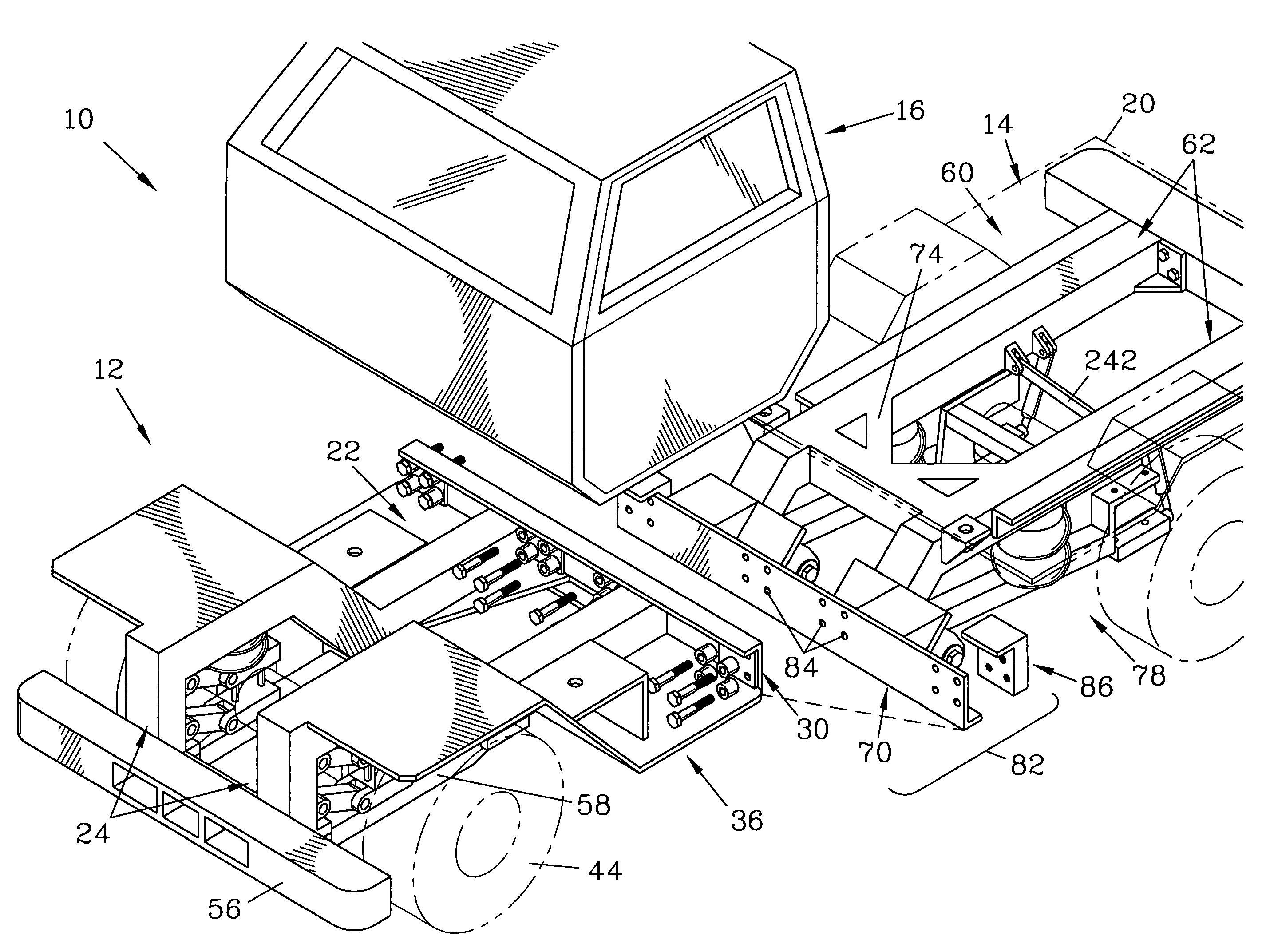
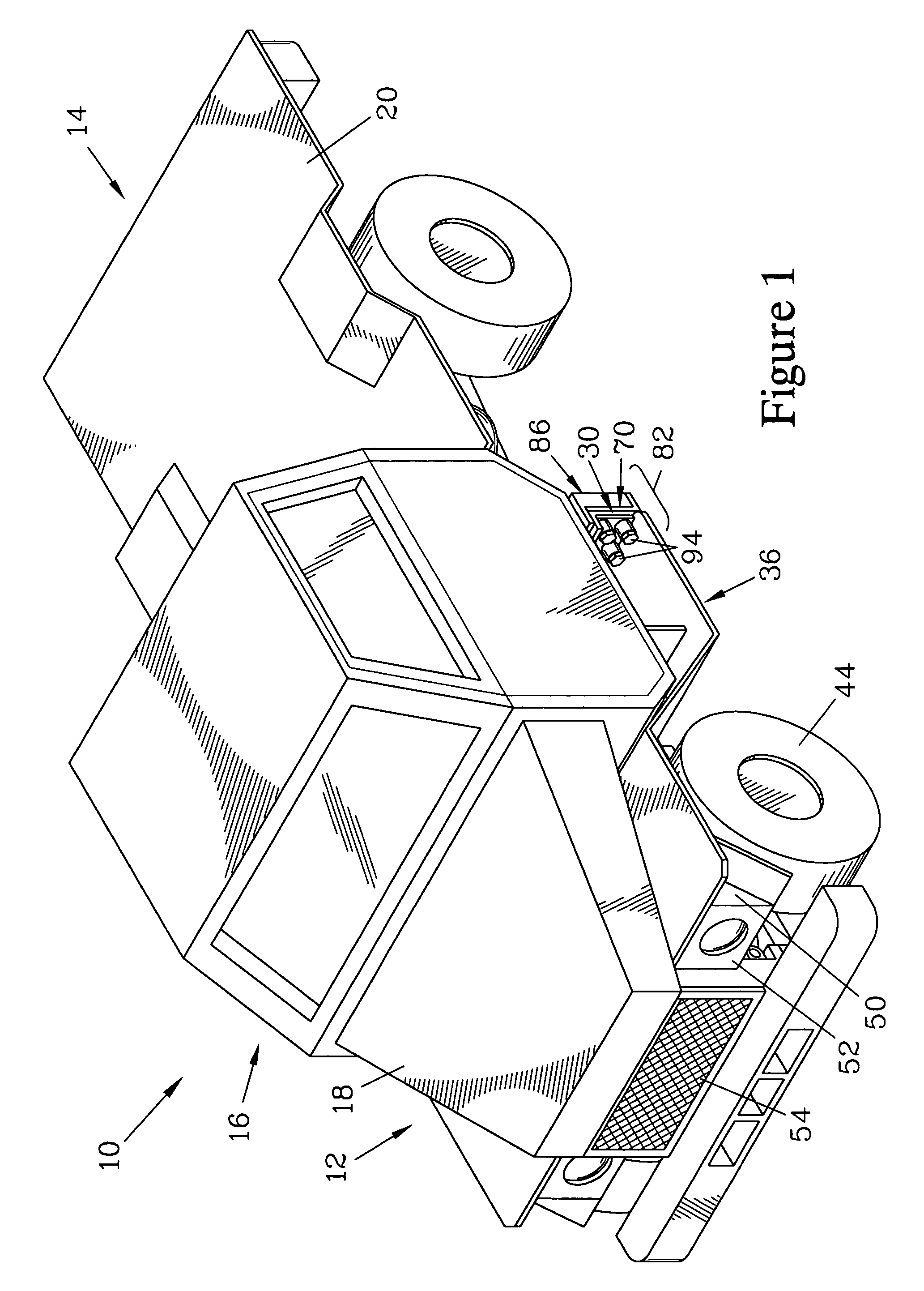
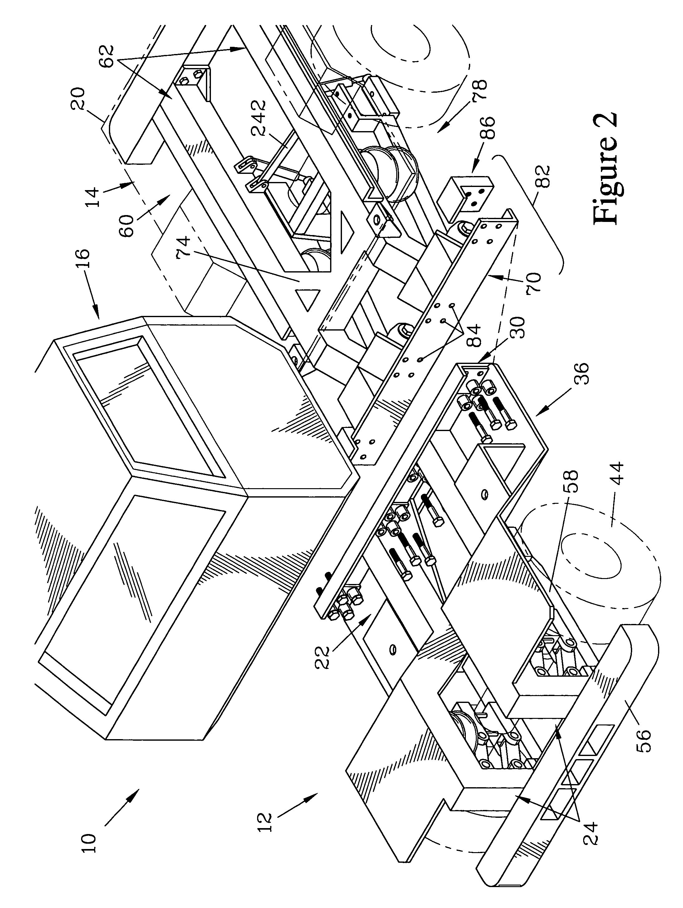
[0009]The present invention is for an improved mine service vehicle which has several features that make it well suited for operation in the underground environments of mines. The vehicle is constructed from modular units which can be readily assembled on-site, allowing larger vehicles to be brought into a mine with
limited access. The modular units have modular
coupling means that allow the modular units to be assembled and disassembled as needed. The use of modular units also allows individual modules to be replaced if damaged, rather than requiring replacement of the entire vehicle. It is further preferred that the vehicle be constructed of at least three modules, a forward module, a rear module, and a cab module. The foreword module houses an engine and includes a cab shield and undercarriage. Alternatively, the forward module could be described as a module configured to house the engine and transmission as well as to provide a ledge extending under a substantial portion of the cab. The forward module is of unitized construction. The rear module couples to the forward module, either directly or via an
intermediate structure, and is fitted with one of a variety of rear
deck or
truck bed configurations, depending on the intended current use of the vehicle. The cab module houses the operator, and cab
coupling means are provided to maintain the cab in position with respect to the forward module and the rear module. Preferably, the cab module is of unitized construction with a cage for the safety of the operator and is so mounted that the operator rides above the cab shield and undercarriage of the forward module. For the added comfort of the operator, the cab
coupling means preferably provide for shock mounting of the cab to the forward module and with respect to the rear module.
[0010]The vehicle of the present invention also provides a rear suspension
system which is configured to better shield a rear axle
assembly of the rear module from damage, as well as to allow for a substantial degree of freedom for movement of the rear axle
assembly to better accommodate movement over uneven terrain, while still maintaining alignment of wheels mounted to the rear axle
assembly. The rear suspension
system has utility for applications beyond the modular mine service vehicle described above. In particular, the rear suspension
system increases the stability of the rear axle against twisting and reduces the need for tie bars between the axle and the frame or complementary leaf springs. This is of particular importance when the wheels are driven.
[0013]The rear module has a rear frame section which has a pair of rear side members, each of which has a rear member horizontal section and a rear member inclined section which is attached to a rear module terminating plate. Each of the rear member horizontal sections preferably terminates in a rear bracket, the rear brackets providing attachment sites for a closure structure of the rear frame section. Such a closure structure can be provided by various elements, such as a bumper or step-down extension, these elements providing additional rigidity for the rear frame section. A cross brace is attached between the rear member horizontal sections in close proximity to the rear member inclined sections. Preferably, the cross brace is a K-brace.
[0017]The cab coupling elements are preferably resilient couplings. In one embodiment, a cab front mounting element attaches to the forward module, and a cab back mounting element attaches to the rear module either directly or, in some situations where the frame is extended via the frame
extender, the cab back mounting element attaches to the frame
extender. The frame extender can also be used to allow a longer cab to be mounted so as to increase the number of passengers that can be accommodated in the cab.
[0019]The above described structure floatably mounts the axle support bars in the
mount bearings and the bracket bearings so as to bias each of the axle support bars toward a
neutral position where the axle support bar resides in a plane to which a nominal pivot axis, defined by the bracket passages, is perpendicular, while allowing substantial twisting motion in directions other than in this plane, and also allowing limited translation along the nominal pivot axis. This resilient, floatable mounting limits sideways movement of the wheels by providing a reaction torque to counter off-axis tilting of the axle support bars. The motion of the wheels is limited, in part, by the
compressibility of the bearing flanges as well as by the
sizing and geometry of the support bar
mount, the axle support brackets, and the bolt. To reduce the amount of sideways movement of the wheels, the separation between each pair of axle support brackets can be increased, with the length of the associated support bar mounts being similarly increased while maintaining a constant
flange thickness for the bearings. Increasing the length of the bearings and the bracket passages will also decrease the sideways movement of the wheels.

