
Multiple-Purpose Vehicle

Active Publication Date: 2022-04-07
KUBOTA LTD
View PDF0 Cites 0 Cited by
  • Summary
  • Abstract
  • Description
  • Claims
  • Application Information

AI Technical Summary

Benefits of technology

The present invention provides a vehicle that can change speed stages for various utility works. It is designed to be convenient for use and has a large intra-case space at the center portion of the transmission case, which makes it easier to assemble the gears inside the case. This results in a more efficient and flexible vehicle for various road conditions.

Problems solved by technology

If the number of speeds for utility works that can be provided by the auxiliary speed changing operations is small, the number of kinds of utility work that can be carried out with using the multiple-purpose vehicle is limited disadvantageously.

Method used


Image

  • Multiple-Purpose Vehicle
  • Multiple-Purpose Vehicle
  • Multiple-Purpose Vehicle

Examples


Embodiment Construction

[0033]Next, an embodiment as an example of the present invention will be explained with reference to the accompanying drawings.

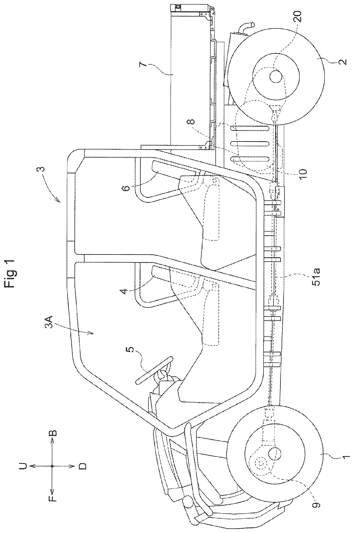
[0034]Incidentally, in the following explanation, with respect to a traveling vehicle body of a multiple-purpose vehicle, the direction of arrow F shown in FIG. 1 is defined as “vehicle body front side”, the direction of arrow B shown therein is defined as “vehicle body rear side”, the direction of arrow U shown therein is defined as “vehicle body upper side”, the direction of arrow D shown therein is defined as “vehicle body lower side”, the direction on the near (front) side of the plane of illustration is defined as “vehicle body left side”, and the direction on the far (back) side of the plane of illustration is defined as “vehicle body right side”, respectively.

[0035][General Arrangement of Multiple-Purpose Vehicle]

[0036]As shown in FIG. 1, the multiple-purpose vehicle includes a traveling vehicle body having a pair of steerable and drivable left and ri...


PUM


Abstract

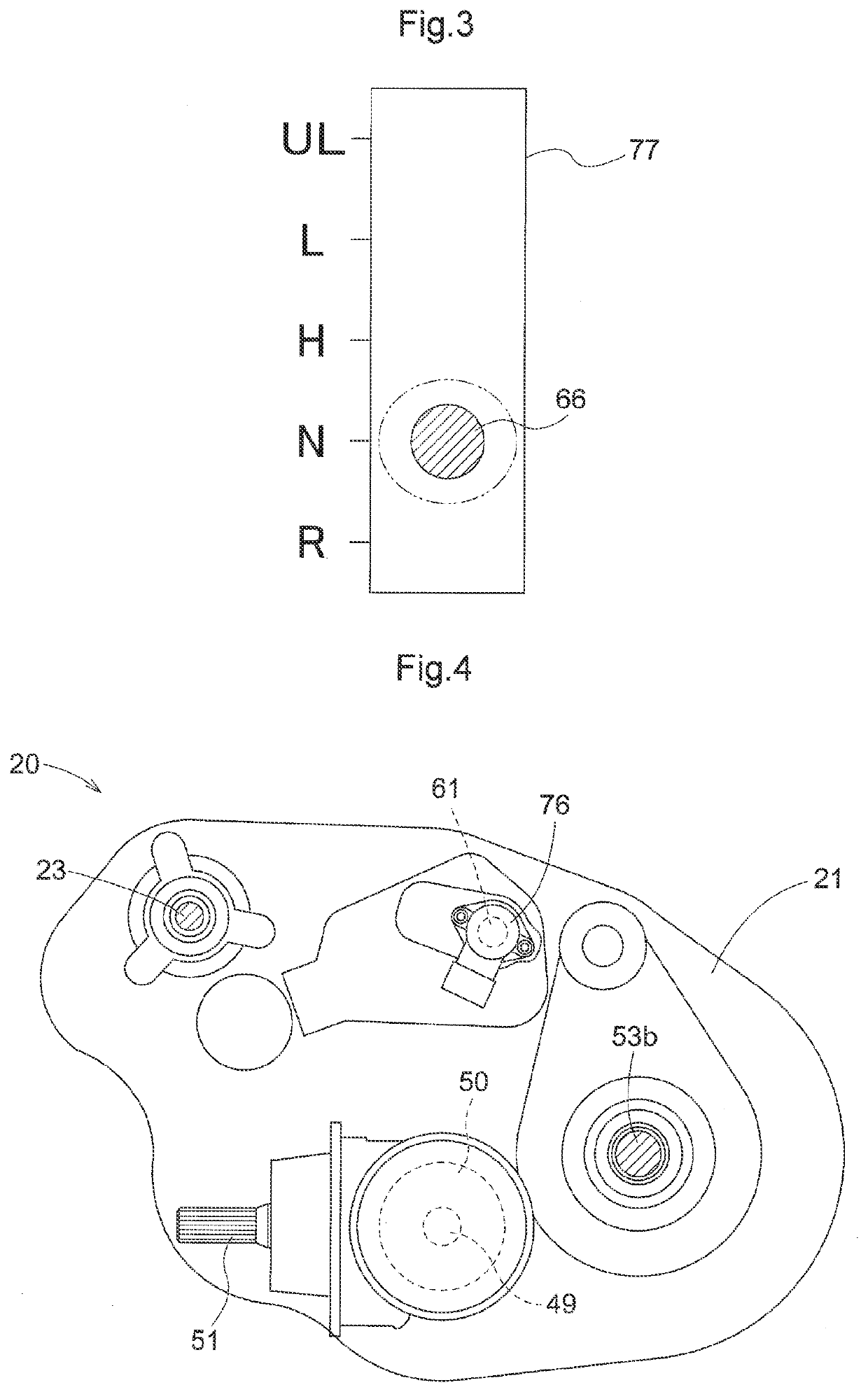
A gear transmission (20) includes a plurality of shift gears (36, 37), a plurality of shifters (55, 56) engaged, respectively, with the plurality of shift gears (36, 37), and a shift drum (58) rotatably operated by a stepped speed changing operational tool (66) to operate the plurality of shifters (55, 56), thus being speed-changed in forward three speed stages. The stepped speed changing operational tool (66) is switched to a neutral position, a forward third speed position, a forward second speed position and a forward first speed position in this cited order.

Description

CROSS-REFERENCE TO RELATED APPLICATION[0001]This application claims priority to Japanese Patent Application No. 2020-168722 filed Oct. 5, 2020, the disclosure of which is hereby incorporated by reference in its entirety.BACKGROUND OF THE INVENTION1. Field of the Invention[0002]The present invention relates to a multiple-purpose vehicle.2. Description of Related Art[0003]A known multiple-purpose vehicle includes a stepless speed changing device and a gear transmission provided in series in a traveling transmission system for transmitting power from an engine to a traveling device and configured to speed-change the power from the engine and transmit the resultant power to the traveling device. The known vehicle further includes a stepless speed changing operational tool for speed-changing operation of the stepless speed changing device and a stepped speed changing operational tool for speed-changing operation of the gear transmission, the stepless speed changing operational tool and t...

Claims


Application Information

Patent Timeline
IPC IPC(8): F16H37/02F16H61/70
CPCF16H37/021F16H2200/0039F16H61/70B60Y2200/20F16H9/14F16H3/089F16H63/18F16H2003/0811F16H2061/047
Inventor YASUDA, TOSHIFUMIMORITA, YUSUKE
Owner KUBOTA LTD
Learn More