Method and plant for pneumatic transport of solid particles

Inactive Publication Date: 2002-09-10
FASTIGHETABBOLAGET AXELN 5
View PDF18 Cites 72 Cited by
  • Summary
  • Abstract
  • Description
  • Claims
  • Application Information

AI Technical Summary

Problems solved by technology

A consequence of this nature is, of course, very serious and consequently it has been elected in respect of known systems to operate the pressurised-air source in a manner to ma

Method used


Image

  • Method and plant for pneumatic transport of solid particles
  • Method and plant for pneumatic transport of solid particles
  • Method and plant for pneumatic transport of solid particles

Examples


case 1

that the temperature dependency is weak, T1=T1=T, and that v1 is directly proportional to the rotational speed as described above==> ##EQU2##

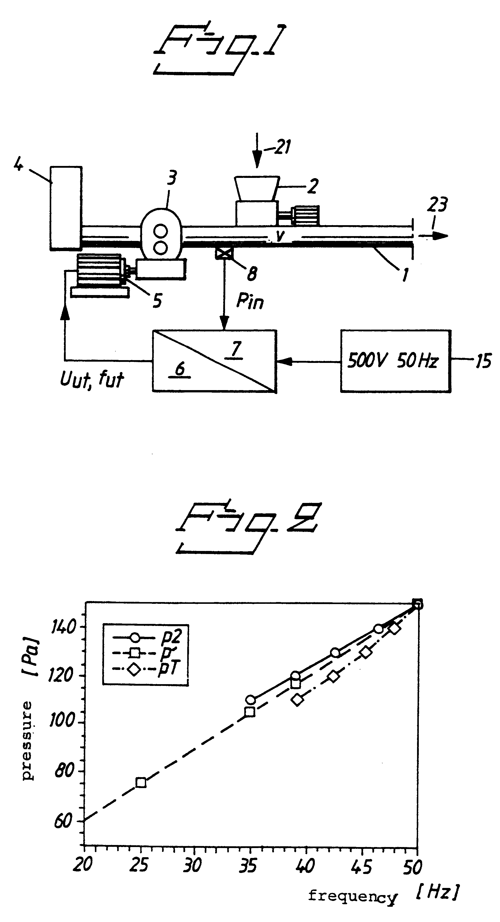
since p1 and v2 are constants. k1 can now be easily determined with data relating to a typical system, e.g. when n=629 rpm at 50 Hz with p2=150 kPa.==>k1=3.

The drawing shows this simple relationship p' which applies approximately at a constant velocity v2=33 m / s (broken line--squares in FIG. 2).

case 2

assume that the temperature dependency is weak, T1=T2=T, and determine v1 as a function of f1 by reading directly from pump curves for the blower concerned. In the case in question, the relationship p2 shown in FIG. 2 by the full line containing circles is obtained.

case 3

se" determination of the relationship that applies to the system. Constant speed v2=33 m / s. Include the temperature T through pV / T=constant, data from pump curves included. Temperature. The relationship between p2 and f1 is given in this case by pT, (shown in FIG. 2 by a broken line that contains rhomboids).

It should be observed that when we directly choose implementation with Case 1-p', the actual velocity at f1=50 Hz will, of course, be v2=33 m / s as it should be. At p2=116.5, f1=38.9 the actual velocity is v2=30.97. The system will herewith run at an idling speed in principle.

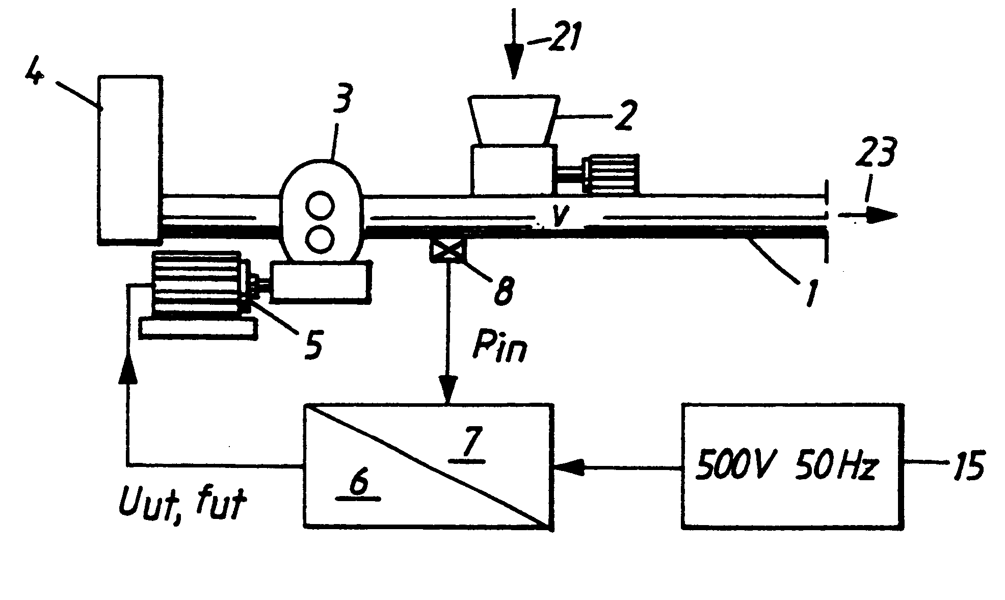
In practical embodiments, several pressure sensors 8 are arranged in the conduit, so as to be on the safe side. The rotary speed of the asynchronous motor may generally vary in the range of (1.0:0.5) times its normal speed, i.e. the frequency can vary from 25-50 Hz since the switch gear normally delivers 50 Hz. The minimum frequency of 25 Hz is then determined with regard to safety against thermal fatigue and...


PUM


Abstract

The present invention provides a method and plant for the pneumatic transportation of solid particles in the form of a diluted phase through a conduit (1), with which the transport air in said conduit is given a velocity which is at most equal to the air velocity chosen for a maximum particle load level. The free flow from the pressurized air source (3) is regulated on the basis of measured air velocity or on the basis of a state corresponding thereto, such as air pressure in the conduit, and an established relationship between the free flow and the said measured velocity of the air or a state (pressure) corresponding thereto, essentially independently of the particle load. There is thus maintained in the conduit a preferably constant transport air velocity with all different occurring levels of particle load.

Description

1. Field of the InventionThe present invention relates generally to a method of transporting solid particles pneumatically. More specifically, the present invention relates to method for pneumatically transporting material in a form of solid particles in a diluted phase through a conduit in which a varying material load arises by the feeding of the particles into the conduit. The particles are driven along the conduit with the aid of an air flow delivered by a pressurized-air source located upstream of a material infeed position.The invention also relates to a corresponding plant system for the pneumatic transportation of material in a form of solid particles in a diluted phase through a conduit. The conduit includes a material infeed device, and a pressurized-air source upstream of the infeed device.2. Related ArtThe transportation of solid particles, such as wood chips, for instance, through a tubular conduit with the aid of a pressurized gas flow, particularly a compressed-air fl...

Claims


Application Information

Patent Timeline
IPC IPC(8): B65G53/66B65G53/34
CPCB65G53/66
Inventor WELLMAR, PAR
Owner FASTIGHETABBOLAGET AXELN 5
Why Eureka
Try Eureka