Ignition coil assembly

Inactive Publication Date: 2002-09-10
HITACHI AUTOMOTIVE PRODUCST USA
View PDF5 Cites 8 Cited by
  • Summary
  • Abstract
  • Description
  • Claims
  • Application Information

AI Technical Summary

Benefits of technology

The magnetic core is constructed from a number of steel laminations which are secured together in any conventional fashion. Unlike the previously known magnetic cores, however, the width of the laminations along the first portion of the magnetic core vary from the top to the bottom of the magnetic core such that the cross sectional shape of the first portion of the magnetic core is substantially circular and of the same size or slightly less than the inside diameter of the primary core bobbin. Thus, since the shape of the portion of the magnetic core extending through the primary and secondary coil subassembly is substantially the same as the inside diameter of the primary coil bobbin, enhanced magnetic coupling between the primary and secondary coils is obtained.
Following assembly of both the primary and secondary coil subassembly and the magnetic core to the housing, a potting material, such as epoxy, is utilized to seal the coils and other components of the ignition coil assembly to protect the ignition coil assembly from the environment.

Problems solved by technology

The use of identical laminations to form the magnetic core results in inexpensive manufacture and assembly costs for the magnetic core.
One disadvantage of these previously known magnetic cores is that the cross sectional shape of the portion of the magnetic core extending through the primary and secondary coils necessarily results in a less than satisfactory magnetic coupling between the primary and secondary coils.
Such spacing reduces the efficiency of the magnetic coupling between the primary and secondary coils.
While such construction increases the efficiency of the magnetic coupling between the coils by reducing the spacing between the top and sides of the magnetic core and the coils, the use of rectangular or square bobbins for the primary and secondary coils creates manufacturing difficulties for winding the primary and secondary bobbins since it is desirable to maintain a constant tension on the wires for the primary and secondary coils during the winding operation.
Such wire tension is difficult to maintain when the bobbins have a square or rectangular cross sectional shape.
A still further disadvantage of the previously known ignition coil assemblies in which the primary and secondary bobbins have a square or rectangular cross sectional shape is that the magnetic coupling between the primary and secondary coils is less efficient than obtainable if the primary and secondary coils are circular in cross sectional shape.

Method used


Image

  • Ignition coil assembly
  • Ignition coil assembly
  • Ignition coil assembly

Examples


Embodiment Construction

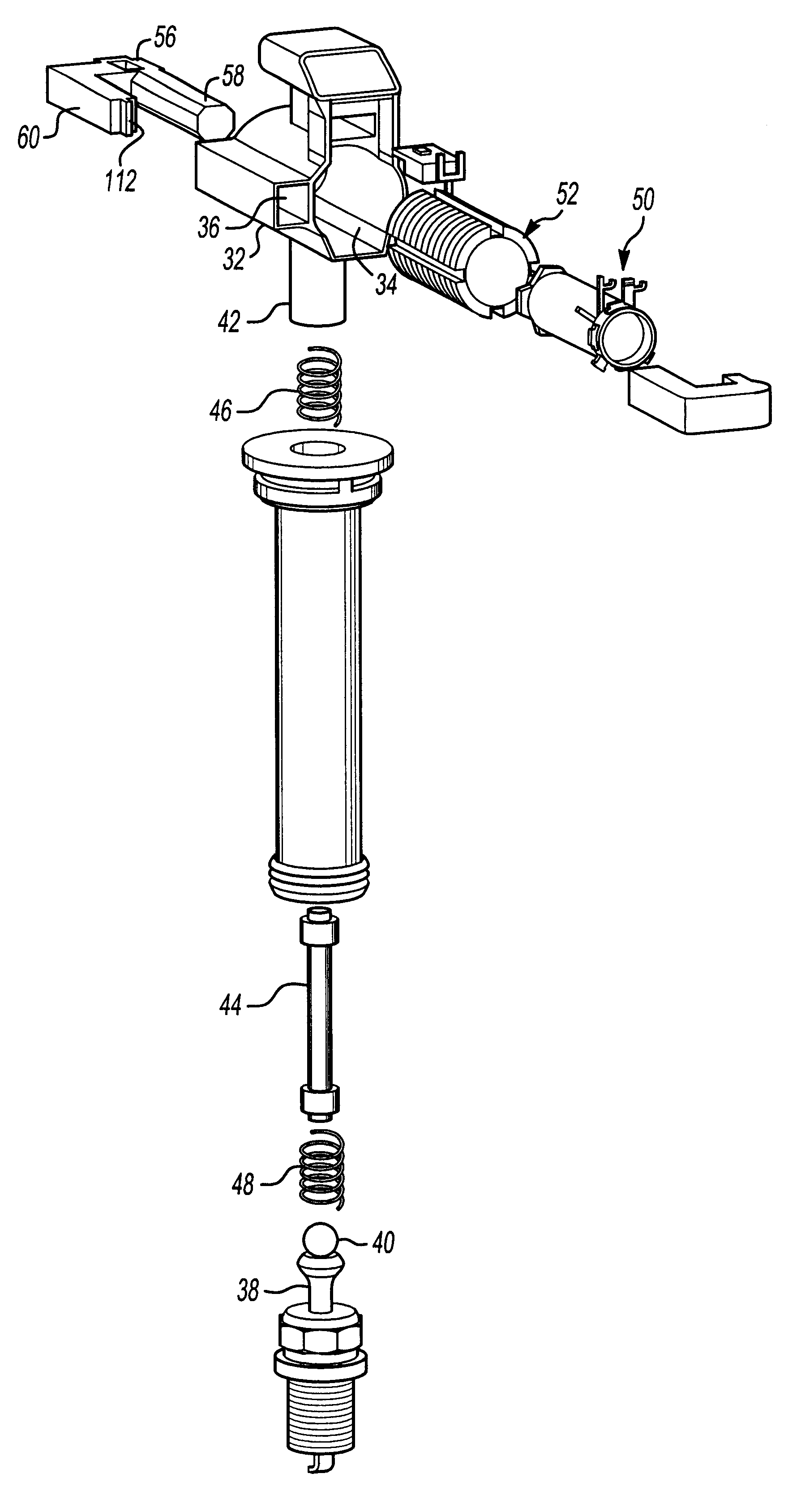
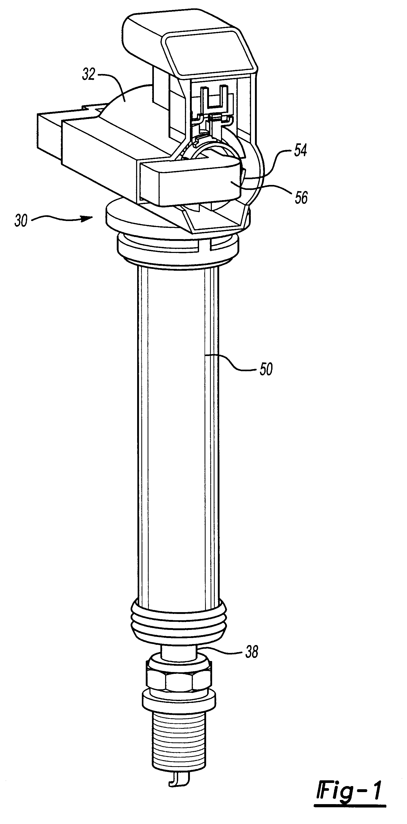
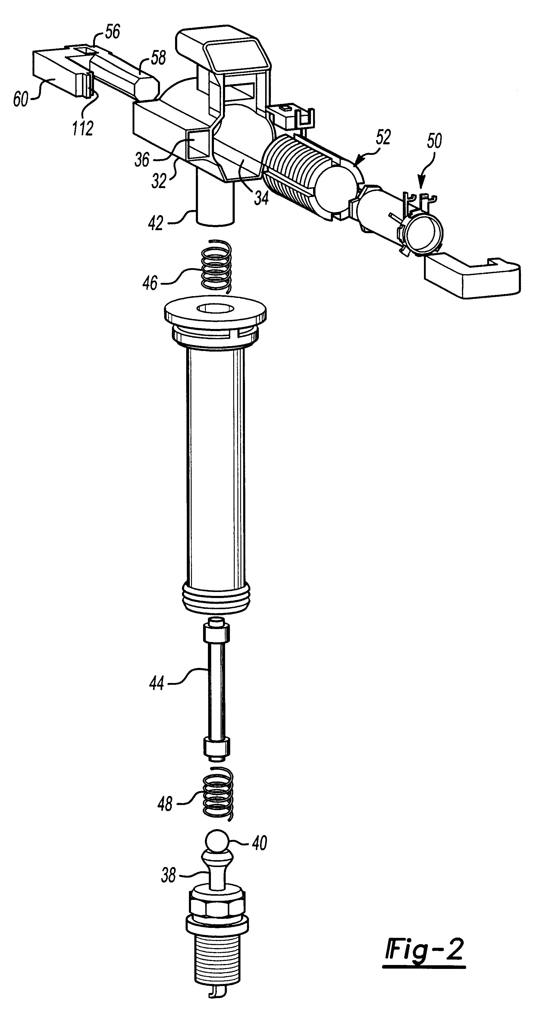
With reference first to FIGS. 1 and 2, a first preferred embodiment of the ignition coil assembly 30 of the present invention is there shown and comprises a housing 32 having a main cylindrical cavity 34 and a square through cavity 36. The housing 32 is constructed of any conventional material, such as plastic.

The ignition coil assembly 30 is designed for use with a single spark plug 38 having a terminal 40. A metal terminal 42 connected to the housing 32 is electrically connected to the spark plug terminal 40 by a metal rigid rod 44 and compression springs 46 and 48. A protective rubber boot 50 is disposed around the metal rod 44 to electrically insulate the metal connection between the housing terminal 42 and the spark plug terminal 40.

Referring now particularly to FIG. 2, the ignition coil assembly 30 further comprises a primary coil assembly 50 which is coaxially disposed within a secondary coil assembly 52 and the primary coil and secondary coil subassembly 54 is then positione...


PUM


Abstract

An ignition coil assembly is disclosed for a spark plug of the type used in internal combustion engines. The ignition assembly includes a housing, a tubular and cylindrical primary coil, and a tubular and cylindrical secondary coil. The primary and secondary coils are each wound on their individual bobbins and the bobbins are mounted in the housing such that the primary coil is coaxially positioned inside the secondary coil. The ignition coil assembly further includes a magnetic core having a first portion which extends through the interior of both the primary and secondary coil and a second portion which extends exteriorly of the primary and secondary coils. The first portion of the coil is substantially circular in cross sectional shape thus matching the circular interior of the primary bobbin. In order to construct the primary coil and secondary coil subassembly, the primary bobbin is first positioned on a winding machine and the primary wire is wound on the bobbin. Thereafter, the secondary bobbin is positioned over the primary bobbin and the wire for the secondary coil is then wound by the winding machine.

Description

I. Field of the InventionThe present invention relates generally to ignition coil assemblies for spark plugs of the type used in internal combustion engines and, more particularly, to an ignition coil assembly of the type used with individual spark plugs.II. Description of the Prior ArtIn the automotive industry, there has been an increased use of distributorless ignition systems in recent years. Such distributorless ignition systems have, in turn, caused an increased use of individual ignition coils for each spark plug of the engine. For example, for a four cylinder engine. four separate ignition coils are utilized. The use of individual ignition coils per spark plug in practice reduces the overall weight of the automobile by eliminating the previously used bulky and heavy single ignition coil used to fire all of the spark plugs in the engine.The use of individual ignition coils per spark plug enables the ignition coil assembly to be relatively compact and lightweight. Such ignitio...

Claims


Application Information

Patent Timeline
IPC IPC(8): H01F27/245H01F38/00H01F38/12
CPCH01F27/245H01F38/12H01F2038/122
Inventor MULLINS, DAVID H.KOGUCHI, HAYATO
Owner HITACHI AUTOMOTIVE PRODUCST USA
Why Eureka
Try Eureka