
Switch having an end of service position in its open state

a technology of switching mechanism and end of service position, which is applied in the direction of heat/cooling contact switch, contacts, electrical equipment, etc., can solve the problems of serious safety risks, switch malfunction is not recognized, and the switch cannot perform its monitoring function

Inactive Publication Date: 2002-09-10
HOFSASS MARCEL
View PDF19 Cites 11 Cited by
  • Summary
  • Abstract
  • Description
  • Claims
  • Application Information

AI Technical Summary

Benefits of technology

Specifically, the inventor of the present application has recognized that by selecting the arrangement and the geometry of the two contact elements, it is possible to ensure that an arc which occurs welds the switch not--as in the prior art--in the closed state, but rather in the open state. This is therefore an departure from measures known from the prior art for preventing an arc; instead, according to the present invention, provision is made for a deliberately directed arc to weld the switch in the open position.
The advantage of this feature is that the current-carrying bimetallic element furthermore ensures that welding is accomplished in the open state in the transition region between still-sufficient opening force and extreme creep. The bimetallic element does not need to work against the force of a closing spring, so that the opening force is still sufficient actually to lift off the movable contact element, even if the bimetallic element has already arrived at the end of its functional service life.
The advantage here is that current flows through a series circuit made up of a temperature-neutral spring element and temperature-dependent bimetallic element; the spring element ensures reliable closing pressure for the closed switch, while the bimetallic element can deform in temperature-dependent fashion without greater mechanical stresses. Furthermore, during switching a transverse movement occurs between the two contact elements, ensuring that the arc which forms initially between the two contact elements is deflected onto the bimetallic element, and then welds the latter to a current-carrying part of the switch.
The advantage here is that the different geometries of the contact elements also deflect the arc from the movable contact element onto the bimetallic element when the opening speed of the switching mechanism weakens as the functional service life is reached. This feature stands in contrast to the features previously believed in the prior art to be indispensable, according to which the contact elements must have a similar and mutually coordinated geometry in order to prevent arcs.
These features once again enhance the reliable formation of an arc which results in welding of the bimetallic element in its second switch position.
In summary, it may be stated that an arc which occurs as the switching capability weakens is deflected from the movable contact element onto the bimetallic element by the differences in geometry between the two contact elements. This effect is further reinforced by a bimetallic element, clamped at one end, that carries the current flowing through the switch, since the contact elements now do not encounter one another centeredly, but rather shift transversely with respect to one another, which enhances deflection of the arc.

Problems solved by technology

If the switching speed is too slow, there can form between the two contact elements an undesirable arc that, in the most unfavorable case, welds the two contact elements to one another so that the switch is permanently closed.
Such a situation is of course undesirable, since it means that the switch can no longer perform its monitoring function.
What is disadvantageous in this context is in particular the fact that this defect of the switch is initially not noticed, since the operating current of the load being protected continues to be carried through the switch.
If the load then heats up to an excessive temperature, the switch can no longer open, which results in serious safety risks.
The malfunction of the switch is not recognized at all until excessive heating of the load occurs, with the damage resulting therefrom.
While the switches with a temperature-dependent switching mechanism switch back on when the load cools off, the blow-out fuses irretrievably open the circuit.
Such additional features are of course cost-intensive, so that they are disadvantageous for that reason alone.
A further disadvantage is the fact that an additional component is necessary in order to monitor the load being protected; this requires physical space that often can be made available only with difficulty or not at all.
When the switching capability of the bimetallic element has weakened in this fashion, there can form between the contact elements an arc which, while at first it is extinguished again, ultimately results--as the switching capability further weakens--in the aforementioned welding of the contact elements.

Method used


Image

  • Switch having an end of service position in its open state
  • Switch having an end of service position in its open state
  • Switch having an end of service position in its open state

Examples


Embodiment Construction

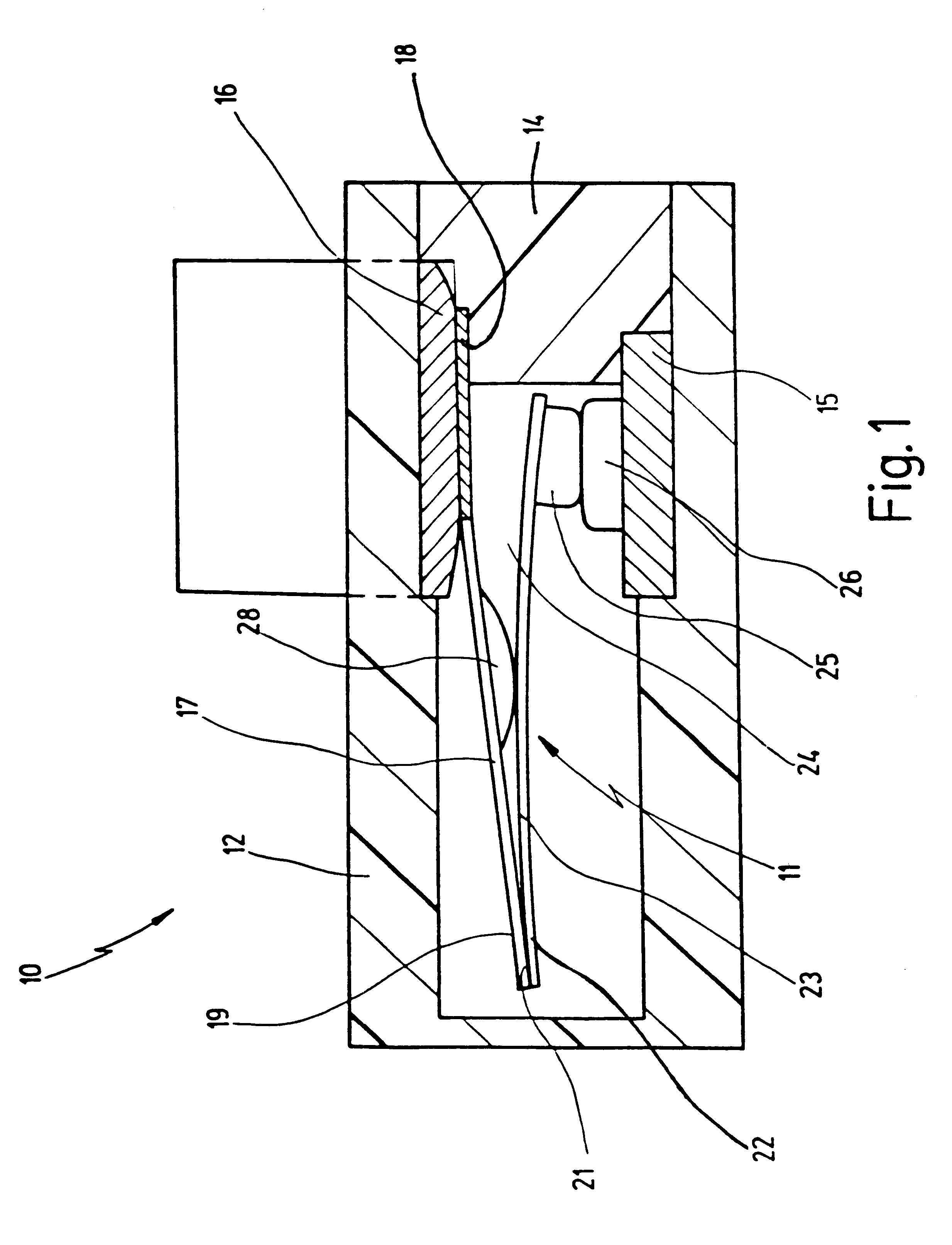
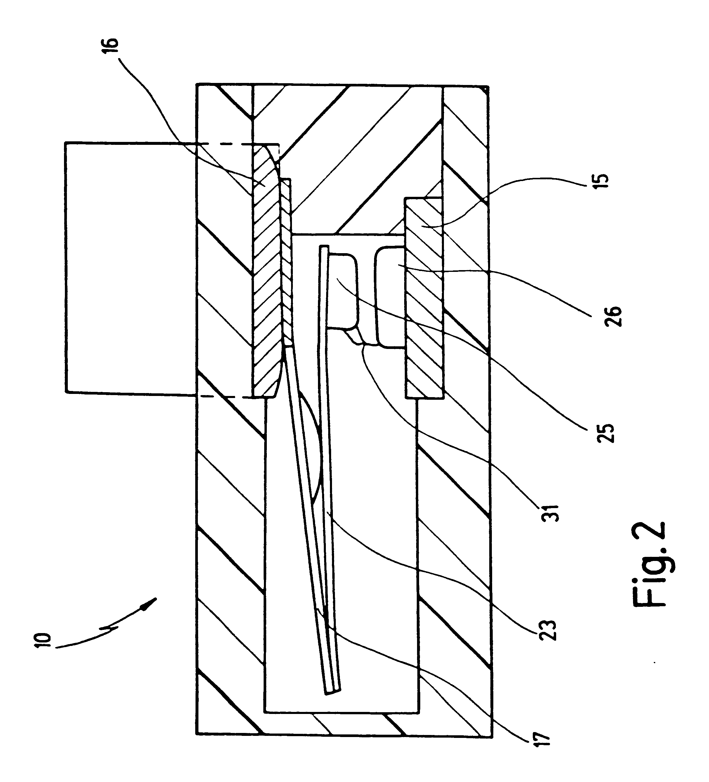
In FIG. 1, 10 designates a switch in a longitudinally sectioned side view. Switch 10 comprises a temperature-dependent switching mechanism 11 that is housed in a plastic housing 12 and is held by a plastic support 14.

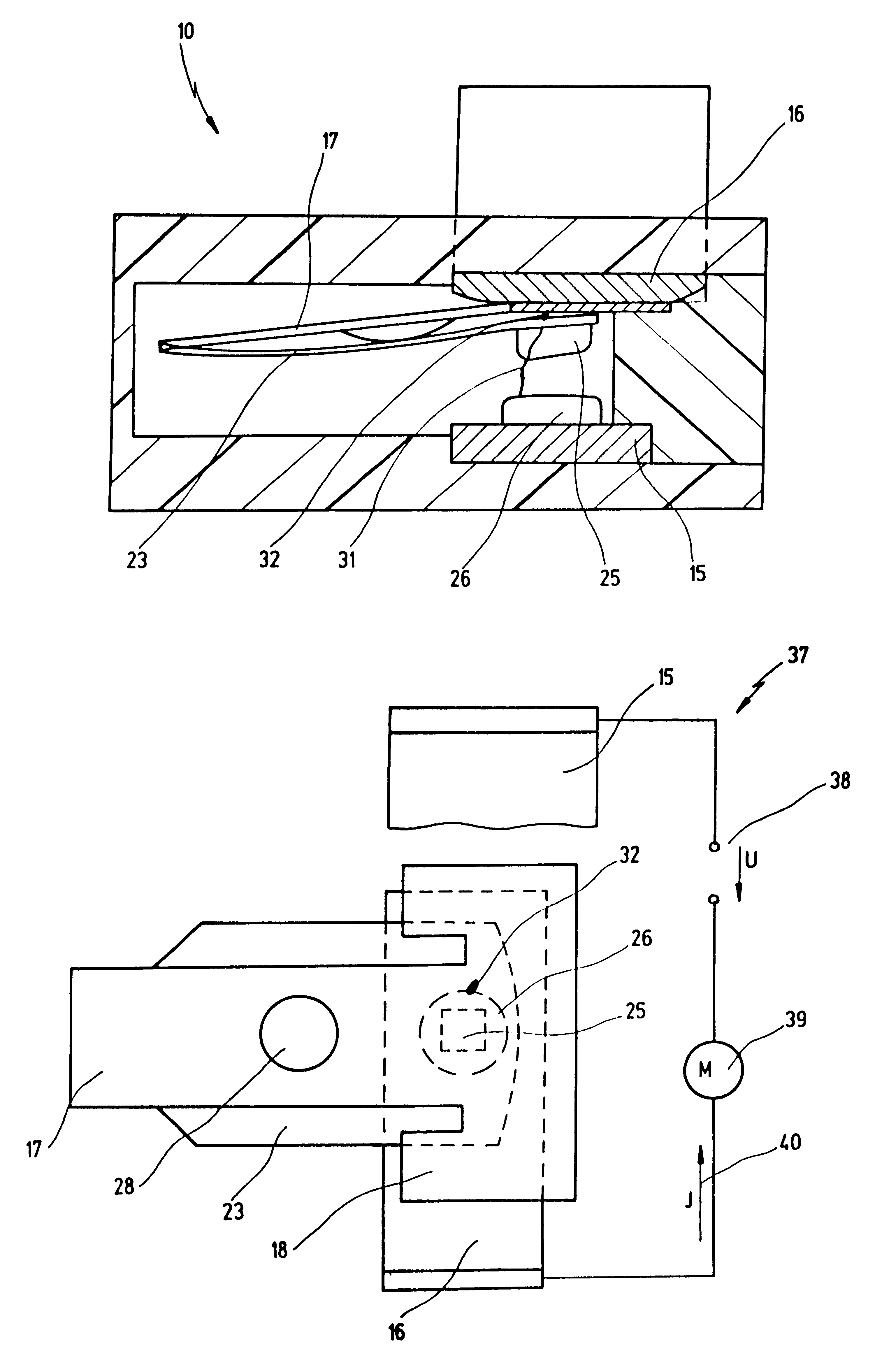
Arranged in plastic housing 12 are a first, lower connection electrode 15 and a second, upper connection electrode 16, between which switching mechanism 11 is electrically and mechanically provided.

Switching mechanism 11 comprises a T-shaped spring element 17 that is clamped with its first end 18, which is configured in the manner of a crossbeam, between plastic support 14 and second connection electrode 16. At its second end 19, spring element 17 has a connection 21 to a first end 22 of a bimetallic element 23 that carries at its free end 24 a movable contact element 25. This movable contact element 25 is associated with a stationary contact element 26 that is mounted on first connection electrode 15.

Spring element 17 and bimetallic element 23 extend, mechanically para...


PUM


Abstract

A switch has a temperature-dependent switching mechanism with a stationary contact element; a movable contact element coacting with the stationary contact element; and a bimetallic element, having a predetermined functional service life, that as a function of its temperature lifts the movable contact element away from the stationary contact element, the two contact elements being, in one switch position, in contact with one another in order to carry a current that is to be guided through the switch, and in a second switch position, lifted away from one another so that the switch is open. The two contact elements are arranged and coordinated with one another in such a way that when the functional service life of the bimetallic element is reached, the switching mechanism is welded in the second switch position.

Description

1. Field of the InventionThe present invention relates to a switch having a temperature-dependent switching mechanism that comprises a stationary contact element; a movable contact element coacting therewith; and a bimetallic element, having a predetermined functional service life, that as a function of its temperature lifts the movable contact element away from the stationary contact element, the two contact elements being, in one switch position, in contact with one another in order to carry or conduct a current that is to be guided through the switch, and in a second switch position, lifted away from one another so that the switch is open.2. Related Prior ArtSwitches of this kind, which are also called temperature controllers or temperature limiters, are commonly known from the prior art.The known switches are used to protect an electrical load from overtemperature and / or excessive operating current. For this purpose it is connected, in series with the electrical load, to a volta...

Claims


Application Information

Patent Timeline
IPC IPC(8): H01H1/00H01H1/50H01H37/00H01H37/54H01H3/00
CPCH01H1/50H01H37/54H01H3/001H01H2001/506H01H2037/5463
Inventor HOFSASS, MARCEL
Owner HOFSASS MARCEL
Learn More