Peak detecting shock gauge and damage diagnostic for mobile and handheld computers

a technology of shock gauge and mobile and handheld computers, which is applied in the direction of portable computer details, instruments, fire alarms, etc., can solve the problems of slider or spindle or actuator bearing damage, device damage, slider or spindle or spindle bearing damage,

Inactive Publication Date: 2002-09-17
IBM CORP
View PDF6 Cites 73 Cited by
  • Summary
  • Abstract
  • Description
  • Claims
  • Application Information

AI Technical Summary

Problems solved by technology

It is well established that excessive shock impacts on electronic devices, such as magnetic disk files, can result in serious damag...

Method used


Image

  • Peak detecting shock gauge and damage diagnostic for mobile and handheld computers
  • Peak detecting shock gauge and damage diagnostic for mobile and handheld computers
  • Peak detecting shock gauge and damage diagnostic for mobile and handheld computers

Examples


Embodiment Construction

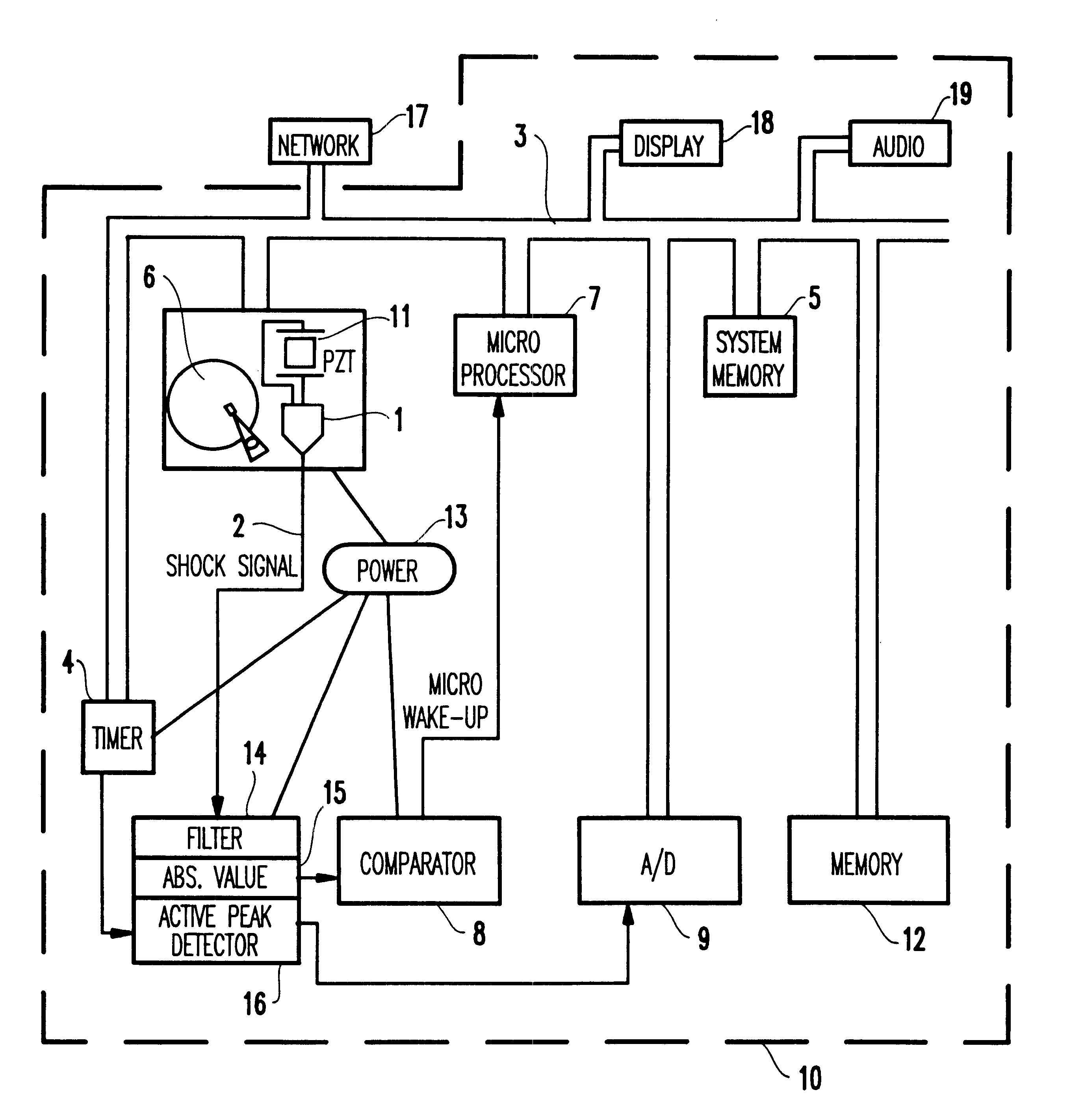
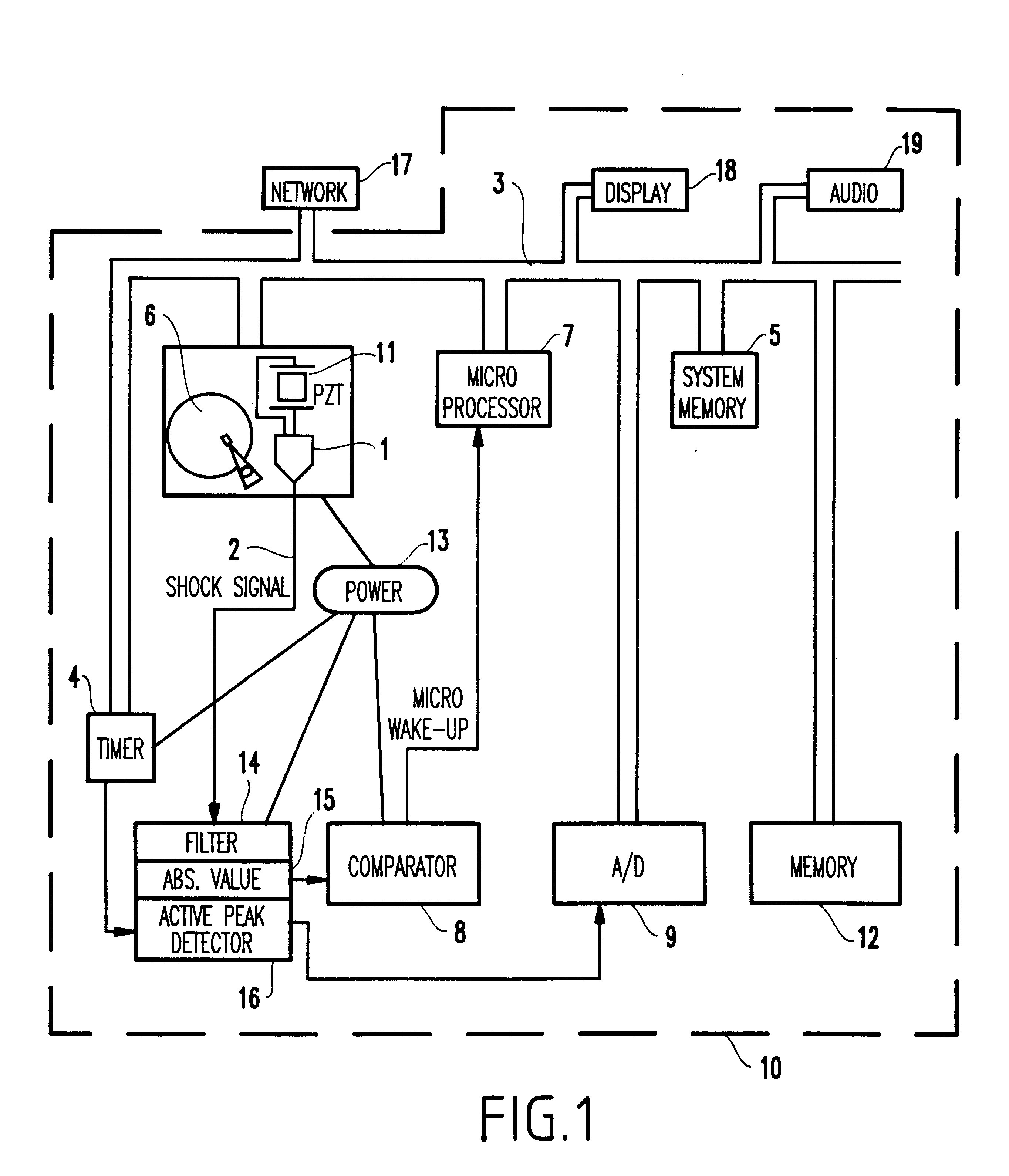
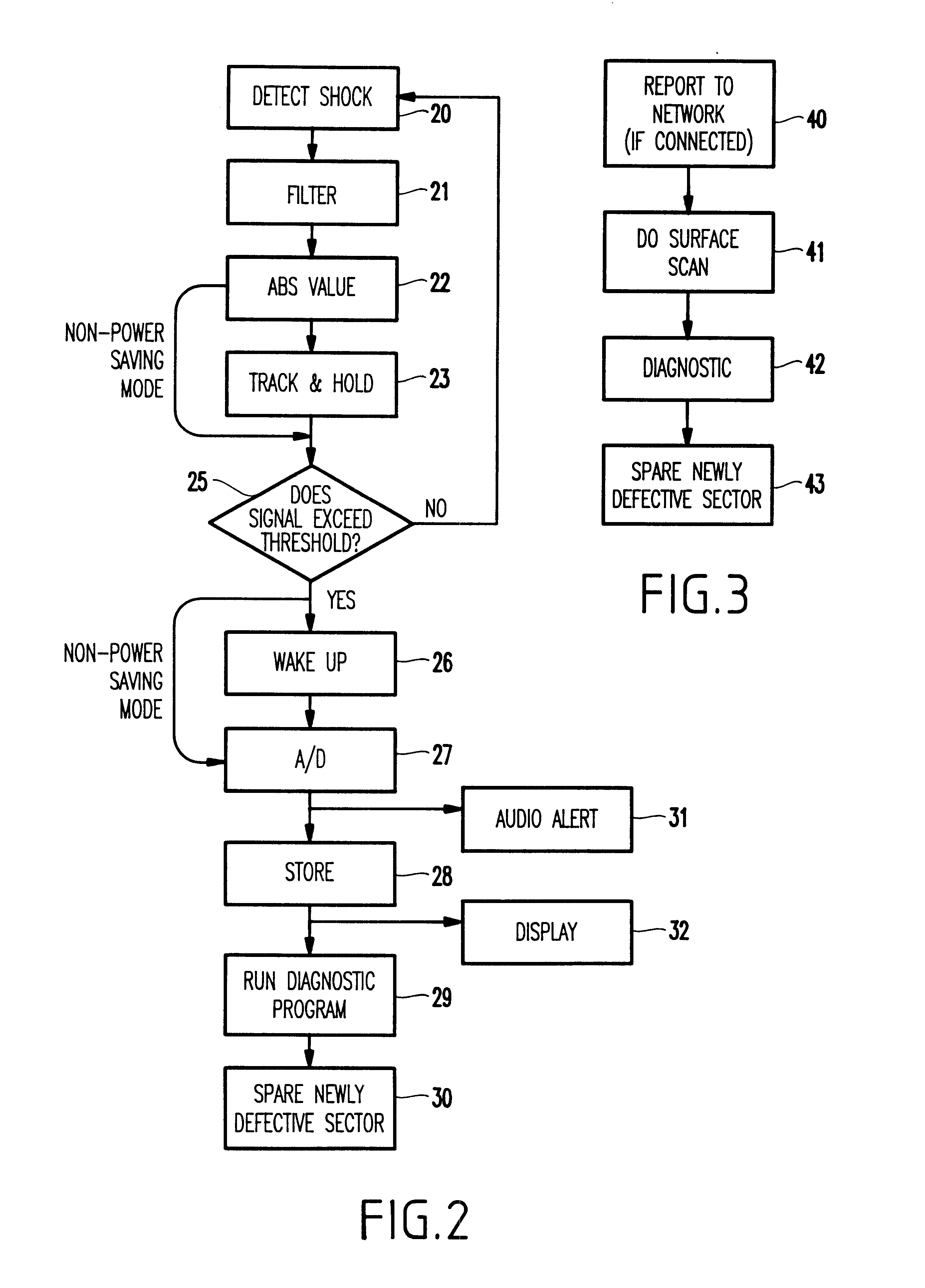
As mentioned above, electronic devices, such as mobile computers and handheld personal digital assistants (PDA) are constantly exposed to a hostile environments and it is sometimes impossible to protect such device against such environments. The invention allows diagnostic tools to be used when a potentially damaging event has been detected and notifies the user to inspect the electronic device for damage. If the consequences of severe environmental conditions shock impacts are detected in time, newly marginal sectors in, for example, a hard drive may be spared. Further, if the electronic device is connected to a network, damage data can be uploaded into an appropriate database and the proper preventive maintenance can be performed automatically. Also, the device can initiate a diagnostic procedure and notify the user of the state of the device.

More specifically, the invention provides the user with a history of abnormal events and warns the user of potential damage. For example, wi...


PUM


Abstract

A method and structure for preventing damage to an electronic device. The structure includes a sensor outputting signals indicating environmental conditions experienced by the electronic device, a non-volatile memory storing ones of the signals that exceed a limit, and an output device outputting signals stored in the non-volatile memory, thereby providing a history of the environmental conditions experienced by the electronic device that exceed the limit.

Description

1. Field of the InventionThe present invention generally relates to damage control systems for electronic devices, such as laptop computers, and more particularly to recording an environmental condition history to determine whether diagnostic programs should evaluate the electronic device.2. Description of the Related ArtIt is well established that excessive shock impacts on electronic devices, such as magnetic disk files, can result in serious damage to the device. For example, impacts to magnetic disk files, may damage the recording surface, slider or the spindle or actuator bearing. To prevent excessive impacts careful handling of the electronic device or its components is required. Additionally, the components within electronic devices can be protected by cushioning material and other shock absorbing devices, such as compliant lossy equipment mounts.Surprising results can be obtained if one measures the acceleration experienced by an electronic device during what is perceived to...

Claims


Application Information

Patent Timeline
IPC IPC(8): G06F1/16
CPCG06F1/1613G06F1/1684
Inventor CHAINER, TIMOTHY JOSEPHETZOLD, KARL-FRIEDRICH
Owner IBM CORP
Why Eureka
Try Eureka