Multi-core optical fiber inspecting method and apparatus

Inactive Publication Date: 2002-09-24
YOKOGAWA ELECTRIC CORP
View PDF5 Cites 16 Cited by
  • Summary
  • Abstract
  • Description
  • Claims
  • Application Information

AI Technical Summary

Benefits of technology

In order to accomplish the object above, according to a first aspect of the present invention, there is provided a multi-core optical fiber inspecting method comprising the steps of putting an optical signal into each incident end core of a multi-core optical fiber having a plurality of cores arranged in one plane, taking out the optical signal emitted from the emission end of the core in a time series mode according to the alignment order of emission-side cores of the multi-core optical fiber, and verifying core numbers of the respective cores of the optical fiber on the basis of the signal patterns thus taken out in the time series mode. Therefore, the coincidence between the alignment order of the input-side cores of the multi-core optical fiber and the alignment order of the output-side cores thereof can be confirmed simply, quickly and accurately.
With the arrangements above, putting the optical signals selectively into the respective cores of the multi-core optical fiber can be carried out easily and quickly in those aforementioned multi-core optical fiber core-number verifying apparatus.

Problems solved by technology

Consequently, much time has been required to take an accurate measurement as extremely complicated preparations for such the measurement are needed.
Moreover, there has been the possibility of making errors in verifying core numbers because the optical output of each core is measured by switching the connections between the light source and the input-side cores.

Method used


Image

  • Multi-core optical fiber inspecting method and apparatus
  • Multi-core optical fiber inspecting method and apparatus
  • Multi-core optical fiber inspecting method and apparatus

Examples


first embodiment

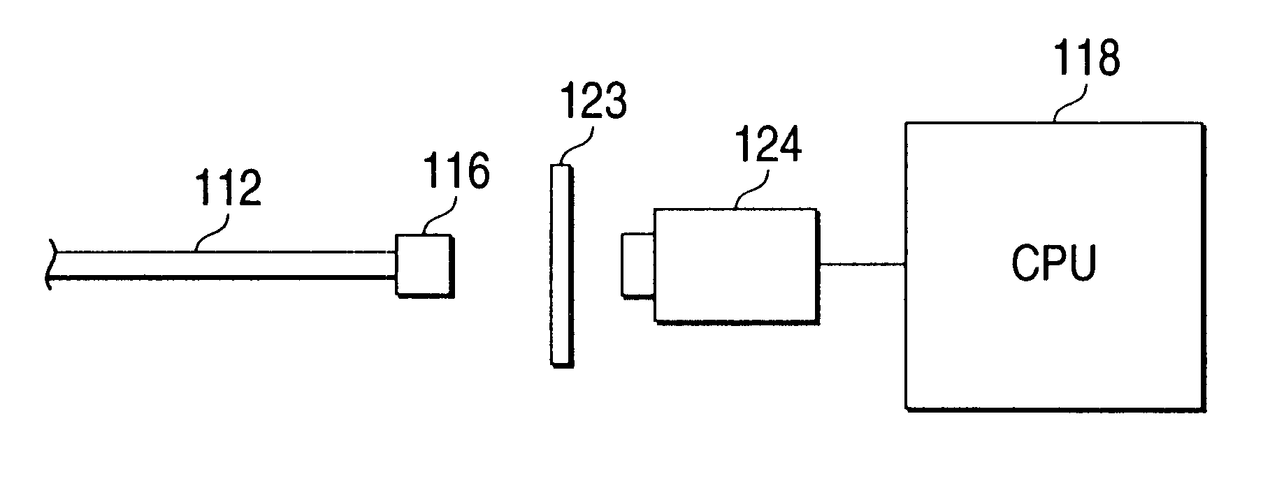
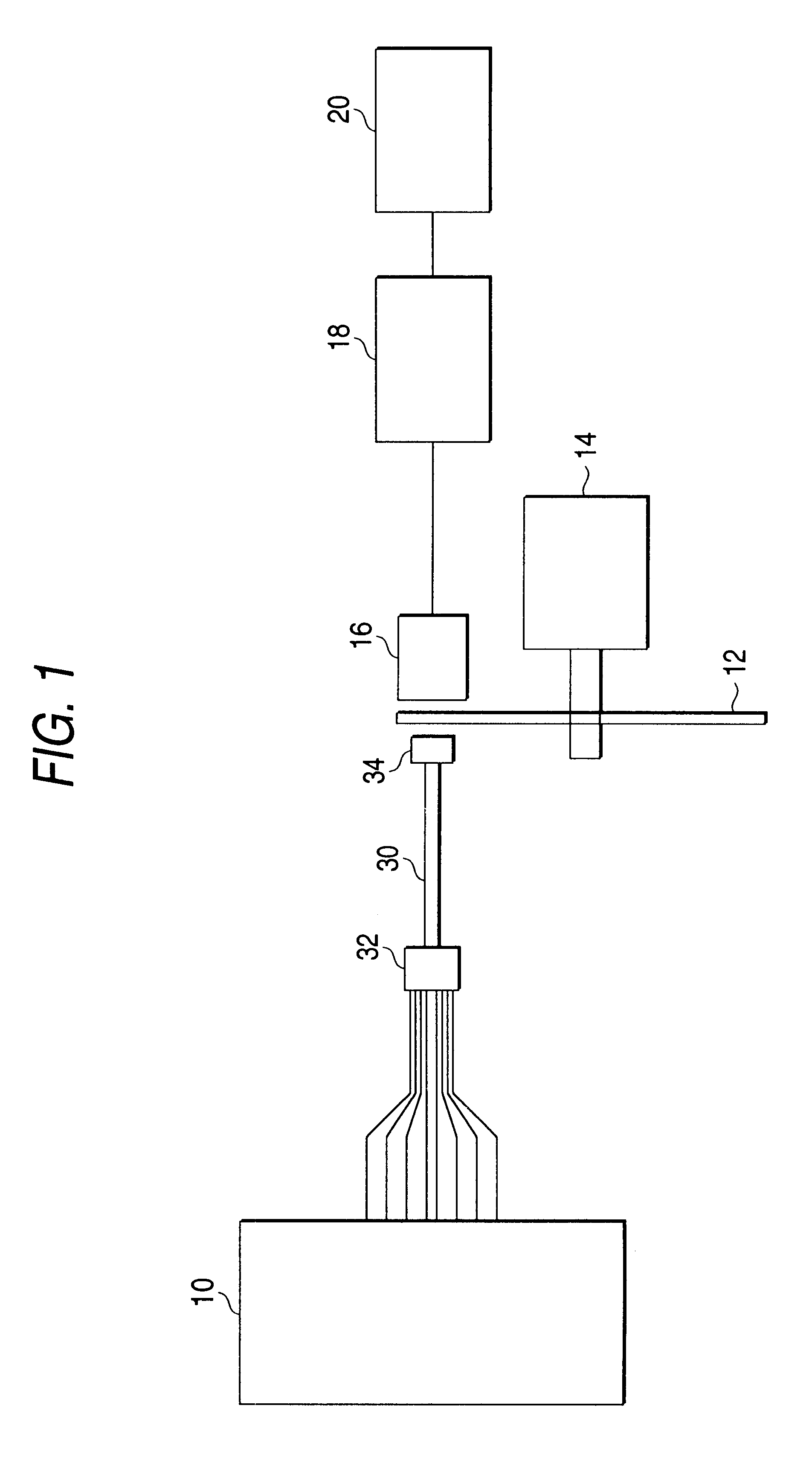
A detailed description of embodiments of the present invention will now be given with reference to the drawings. FIGS. 1 and 2 show a multi-core optical fiber inspecting apparatus as the invention. In the multi-core optical fiber inspecting apparatus according to this embodiment of the invention, an optical signal is input to the incident end of each of the cores of a multi-core optical fiber having a plurality of cores arranged in one plane and the optical signals that are output from the respective emission ends of these cores are taken out in time series according to the alignment order, so that each of the core numbers is verified on the basis of the signal patterns thus taken out in time series.

As shown in FIG. 1, a multi-core optical fiber 30 has the plurality of cores arranged in one plane and both its ends are connected to connectors 32 and 34, respectively.

The multi-core optical fiber inspecting apparatus has a multi-output light source unit 10 having a plurality of optical...

second embodiment

According to the invention, it is possible to confirm the coincidence between the alignment order of the input-side cores of the multi-core optical fiber and the alignment order of the output-side cores thereof and to measure the transmission loss of the optical fiber as its basic characteristic in one step simply, quickly and accurately.

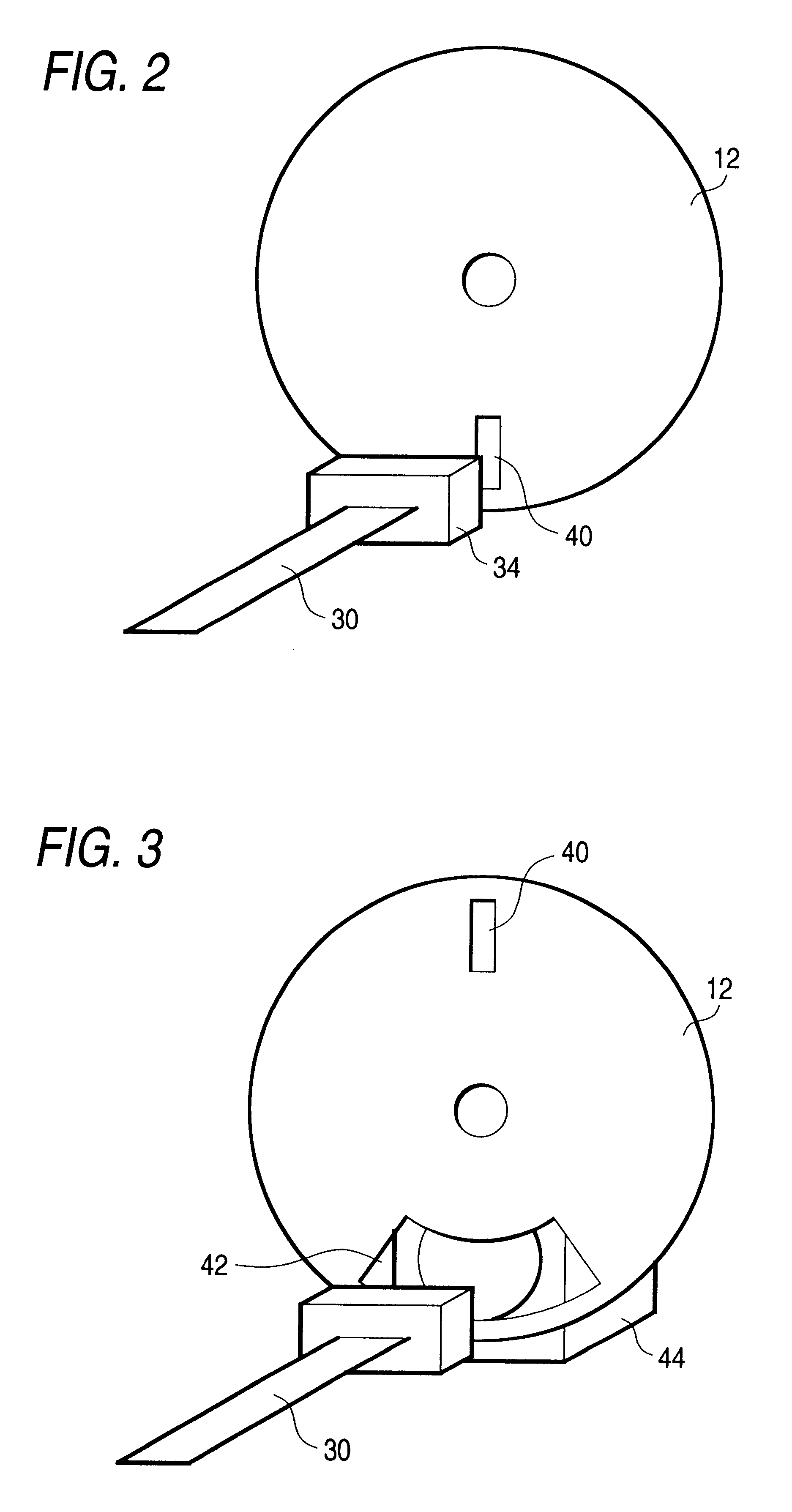
A multi-core optical fiber inspecting apparatus as a third embodiment of the invention will be described. What makes the multi-core optical fiber inspecting apparatus according to this embodiment of the invention different from the multi-core optical fiber inspecting apparatus according to the second embodiment of the invention is that a photocoupler 46 for generating a reference signal for use in detecting the position of each core of the multi-core optical fiber 30 is as shown in FIG. 4 disposed in a position where the slit 40 formed in the rotary plate 12 crosses the optical path formed by the photocoupler 46 when the slit 40 rotates, wherein as ...

third embodiment

According to the invention, it is possible to confirm the coincidence between the alignment order of the input-side cores of the multi-core optical fiber and the alignment order of the output-side cores thereof simply, quickly and accurately.

A multi-core optical fiber inspecting apparatus as a fourth embodiment of the invention will now be described with reference to FIG. 6. This embodiment of the invention is intended to realize a specific measurement method for verifying core numbers of multi-core optical fibers, and an apparatus therefor may be arranged according to any one of the first to third embodiments. However, the repeated description of such apparatus will be omitted.

FIGS. 6A to 6D show patterns of optical signals to be produced in time series from the respective cores of the multi-core optical fiber 30 at the time of verifying the core numbers. In FIGS. 6A to 6D, reference numeral 102 denotes a multi-core optical fiber output signal. FIG. 6A shows a condition wherein the...


PUM


Abstract

An apparatus for inspecting a multi-core optical fiber having a plurality of cores arranged in one plane includes a light source 10 having a plurality of optical output terminals which are connected to the incident ends of the respective cores of the multi-core optical fiber and used for putting optical signals into the respective cores thereof; optical signal taking means (12 and 14) for taking out the optical signal emitted from the emission end of each core of the multi-core optical fiber in a time series mode according to the alignment order of emission-side cores of the multi-core optical fiber; optical signal detecting means (16 and 18) for detecting the optical signal thus taken out by the optical signal taking means; and signal processing means 20 for verifying core numbers of the respective cores of the multi-core optical fiber on the basis of the signal patterns of detection outputs of the optical signal detecting means.

Description

1. Field of the InventionThis invention relates to a multi-core optical fiber inspecting method and apparatus, and more particularly, to a multi-core optical fiber inspecting method and apparatus for confirming the coincidence between the alignment order of input-side cores of a multi-core optical fiber and the alignment order of output-side cores of the multi-core optical fiber for use as an optical communication medium, and for measuring a transmission loss of each core in one step.2. Description of the Related ArtA multi-core optical fiber is prepared by aligning a plurality of optical fiber cores in the form of a tape in one plane. In the case of such a multi-core optical fiber, the alignment order of input-side cores is required to coincide with the alignment order of output-side cores Supposing that the alignment order of input-side cores is not coincident with the alignment order of output-side cores, it would be impossible to transmit optical signals to any target transmissi...

Claims


Application Information

Patent Timeline
IPC IPC(8): G02B6/38
CPCG02B6/3807
Inventor OHKI, KAZUHIROIIDA, RIKIHIRO
Owner YOKOGAWA ELECTRIC CORP
Why Eureka
Try Eureka