Paddlewheel fish deterrent and guide

a technology of deterrent and guide, which is applied in pisciculture, pisciculture and aquaria, and marine site engineering, etc. it can solve the problems of increasing the overall bypass effectiveness, difficult to obtain with point source sound generators and current inducers, etc., and achieves convenient coexistence, convenient deployment, and relative portability.

Inactive Publication Date: 2002-10-01
TRUEBE JONATHAN P +1
View PDF30 Cites 14 Cited by
  • Summary
  • Abstract
  • Description
  • Claims
  • Application Information

AI Technical Summary

Benefits of technology

(d) The system is relatively portable and can easily be deployed for the fish migration period.
(e) The paddlewheel deterrent and guide can also coexist easily with routine hydroelectric plant operations. In many instances, it is difficult to operate fish protection devices because debris in the river damages them, or devices such as screens are clogged by debris. But the creation of turbulence upstream of the paddlewheel keeps most floating debris away from the intake and sluices it down the fish bypass. The paddlewheel will simply "walk over" or "walk under" the large debris that is not influenced by the turbulence.
(f) This system is likely to keep fish in a natural river environment. This results in a reduction of disease transmission

Problems solved by technology

(a) The invention operates based on a number of behavioral deterrent principles. Therefore, there is a backup if conditions change and one of the deterrents is ineffective. Therefore, this increases the overall bypass effectiveness.
(b) The turbulence and sound fields can easi

Method used


Image

  • Paddlewheel fish deterrent and guide
  • Paddlewheel fish deterrent and guide
  • Paddlewheel fish deterrent and guide

Examples


Embodiment Construction

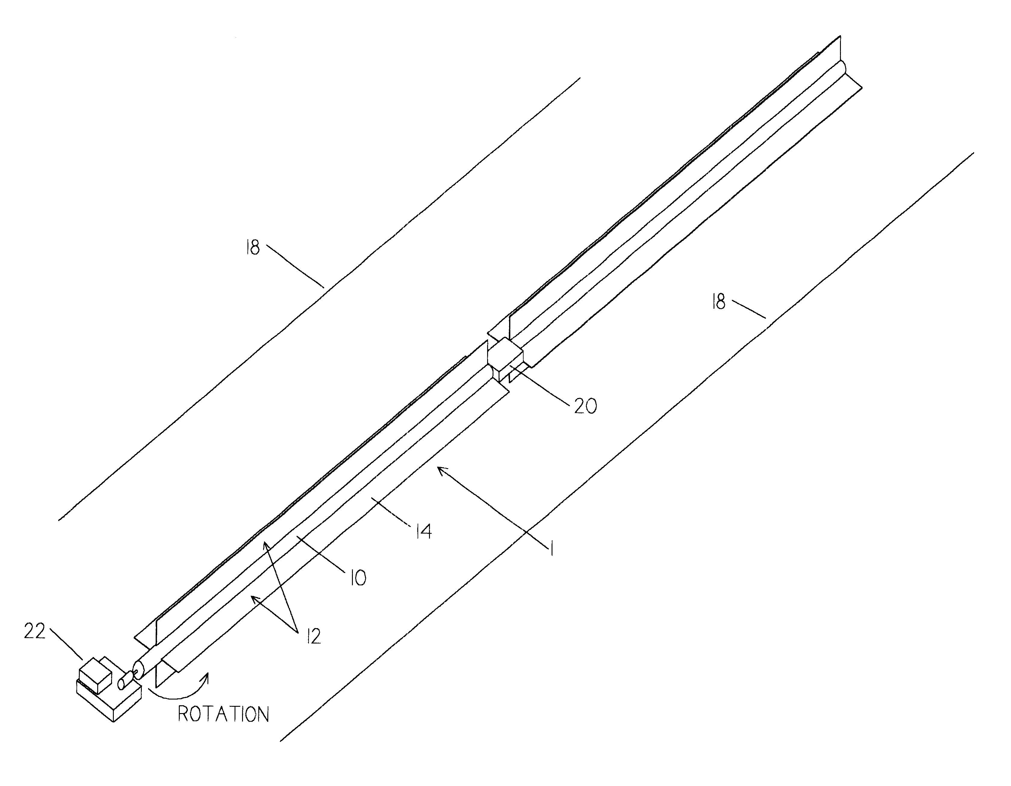
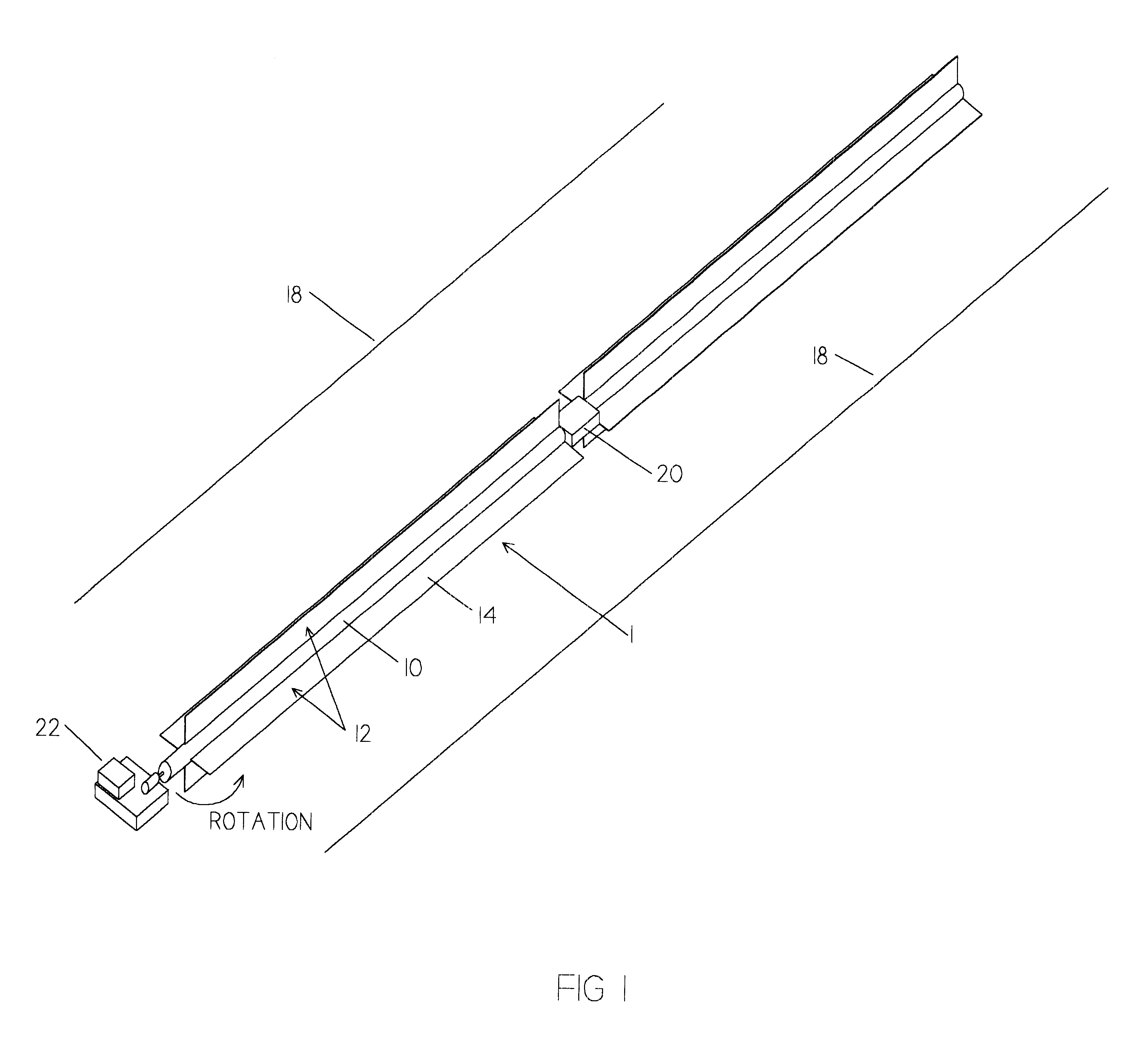
FIG. 1 shows a perspective view of the present invention, a paddlewheel fish deterrent and guide. A paddlewheel 1 is comprised of a central shaft 10, extending from which is a series of vanes 12. Each vane 12 is constructed of a flat plate 14 extending out along the length of central shaft 10 in a manner similar to a conventional waterwheel. Alternatively, this plate may be curved to improve the hydrodynamics of paddlewheel 1. Paddlewheel 1 is of sufficient buoyancy or is suspended from an adjacent structure such that the midpoint of shaft 10 is located at water surface 18. Paddlewheel 1 is constructed short enough to facilitate handling. Sufficient numbers of sections of paddlewheel 1 are connected to one another to span the hydroelectric intake area. Power transmission between the sections of paddlewheel 1 is achieved by a universal joint 20. Construction materials for central shaft 10 and vanes 12 may be of any material that is neutrally buoyant and has sufficient rigidity to tra...


PUM


Abstract

An improved fish deterrent and guide, utilizing generally a paddlewheel (1) consisting of a central shaft (10) with vanes (12) to create a behavioral modifier. When paddlewheel (1) is rotated, the action of the vanes striking the water creates water particle motion (low frequency sound or infrasound), turbulence and current, as well as visual cues that fish avoid. The device is tunable for different fish species and life stages by adjustment of vane style, spacing, and paddlewheel rotation speed. The use of multiple behavioral deterrents creates a measure of reliability in the system. Another advantage is that this fish deterrent provides a continuous lead, which is more effective than typical point-source turbulence and sound generators. Typically, the paddlewheel fish deterrent and guide is positioned at the water surface across the intake to a power plant intake to deter surface oriented downstream migrating fish, and guide them to a bypass. In this configuration floating debris is also guided through the bypass. Alternatively, the paddlewheel may be positioned at a subsurface elevation to guide non surface oriented fish to the bypass, or positioned across the tailrace to guide upstream migrating fish to a fishway entrance.

Description

BACKGROUND--FIELD OF THE INVENTIONThis invention relates to modifying the behavior of fish. Specifically, it modifies fish behavior by using oscillating water particle acceleration, visual cues, and water currents.BACKGROUND--DESCRIPTION OF PRIOR ARTSystems have been designed and installed to deter or guide fish from certain underwater areas. These areas include water intakes for hydroelectric power plants, municipal water intakes, thermal power plants, and irrigation systems. Fish can suffer high mortalities when they come in contact with pumps or turbines, when they are subject to temperature variations induced by plants, or when they are pumped through irrigation systems and discharged onto fields.These systems used to deter or repel fish can be broken down into two categories: physical barriers and behavioral deterrents. These devices and their advantages and disadvantages are described in Taft, E.P. 1986. Assessment of Downstream Migrant Fish Protection Technologies for Hydroel...

Claims


Application Information

Patent Timeline
IPC IPC(8): A01K61/00E02B1/00
CPCA01K61/00E02B1/006A01K79/02Y02A40/81E02B8/085Y02A40/60A01K61/10
Inventor TRUEBE, JONATHAN P.TRUEBE, ERIC P.
Owner TRUEBE JONATHAN P
Why Eureka
Try Eureka