Apparatus and method for directing airflow in three dimensions to cool system components

a technology of three dimensions and airflow, applied in the direction of lighting and heating apparatus, electrical apparatus casings/cabinets/drawers, instruments, etc., can solve the problems of affecting the effectiveness of the cooling mechanism, the type of cooling mechanism suffers several drawbacks, and the internal system temperature rises

Inactive Publication Date: 2002-10-01
JUMIPER NETWORKS INC
View PDF14 Cites 209 Cited by
  • Summary
  • Abstract
  • Description
  • Claims
  • Application Information

AI Technical Summary

Problems solved by technology

During operation, the electronic components in these systems dissipate heat, causing the internal system temperature to rise.
This type of cooling mechanism, however, suffers several drawbacks.
First, the effectiveness of the cooling mechanism may be affected by the location of the air inlet.
In these cases, the cooling mechanism draws in heated a...

Method used


Image

  • Apparatus and method for directing airflow in three dimensions to cool system components
  • Apparatus and method for directing airflow in three dimensions to cool system components
  • Apparatus and method for directing airflow in three dimensions to cool system components

Examples


Embodiment Construction

refers to the accompanying drawings. The same reference numbers in different drawings identify the same or similar elements. Also, the following detailed description does not limit the invention. Instead, the scope of the invention is defined by the appended claims and equivalents.

EXEMPLARY APPARATUS

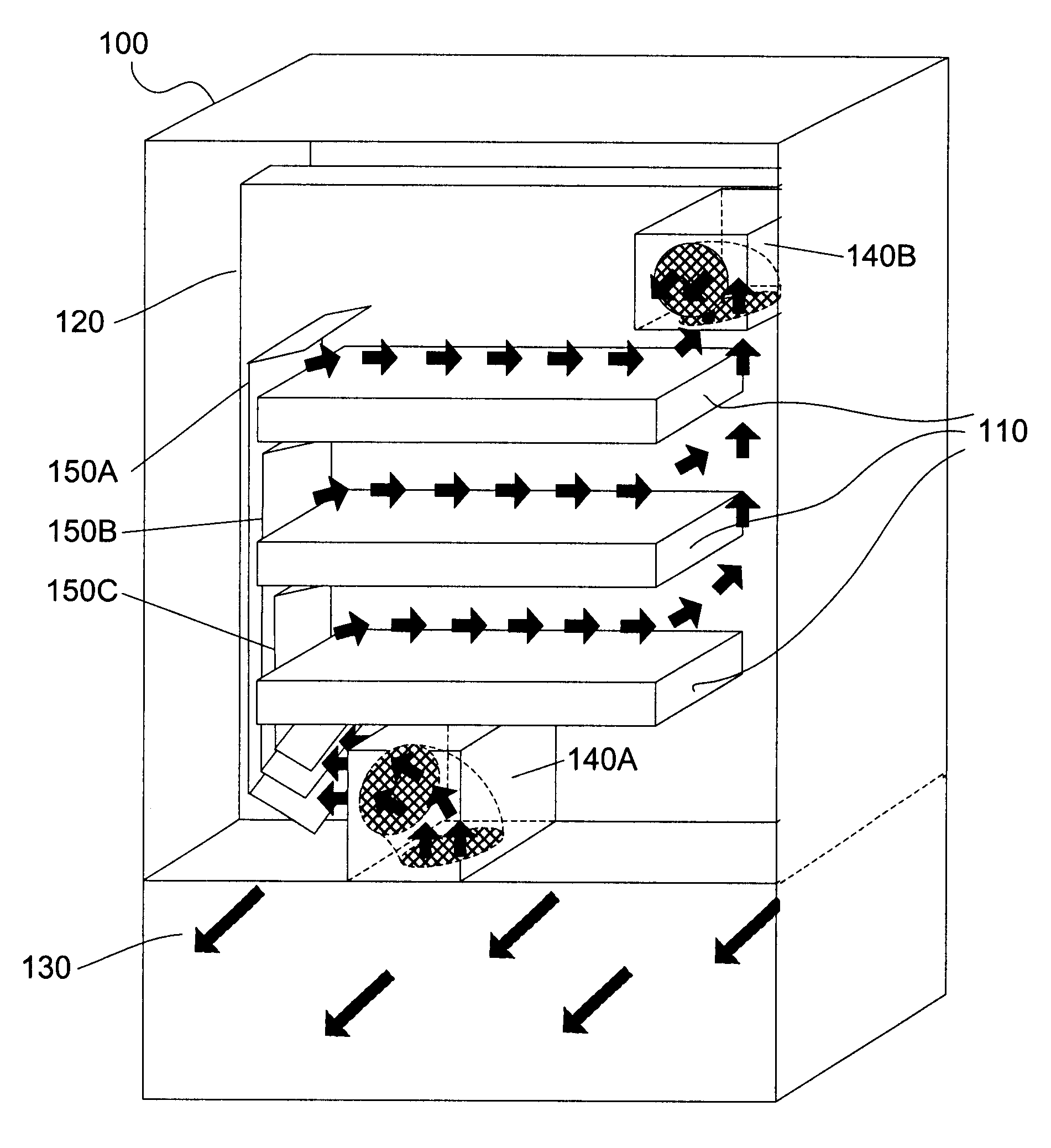
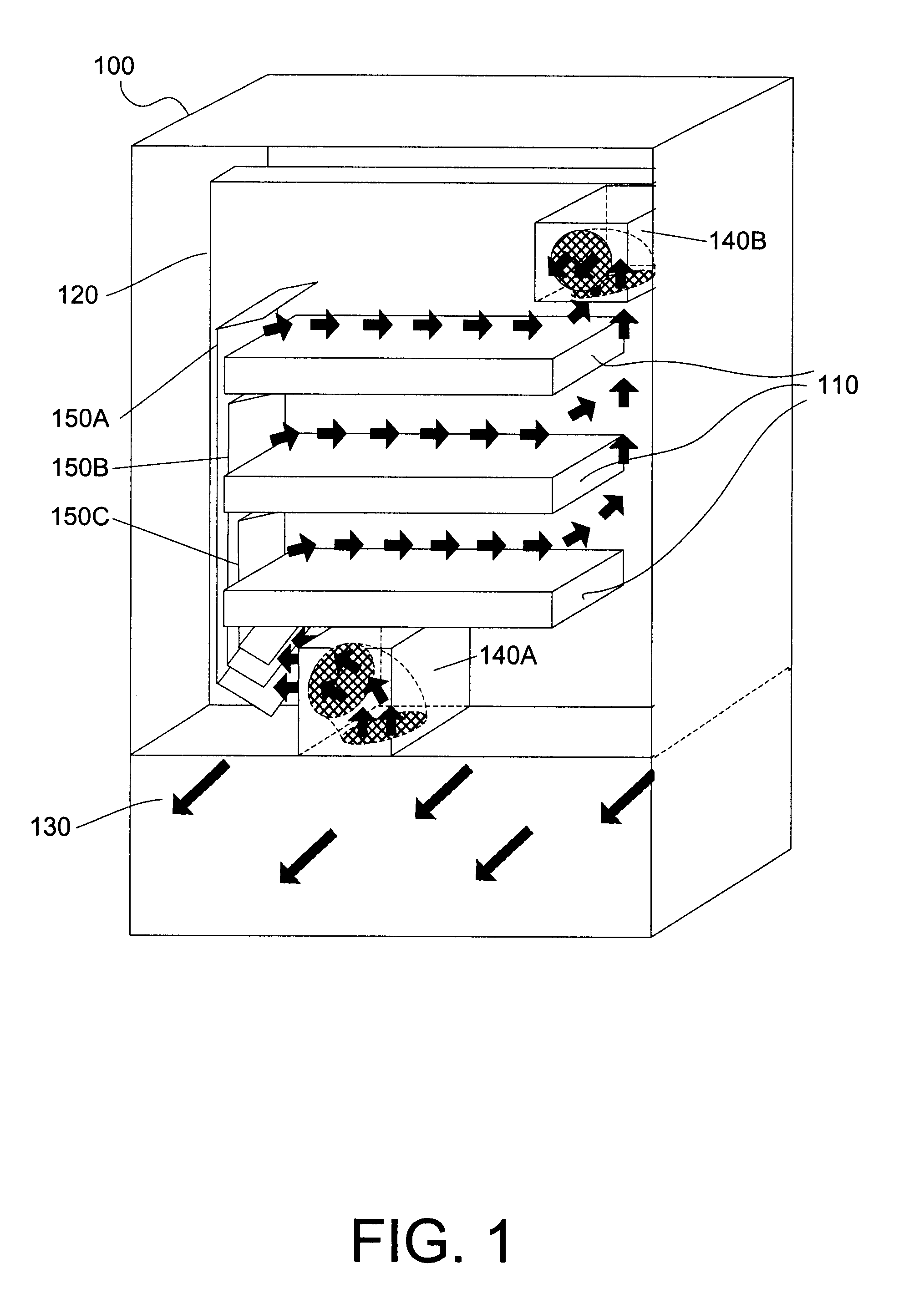
FIG. 1 shows a perspective view of an exemplary system 100 in which the invention may be used. As shown in FIG. 1, system 100 includes a plurality of circuit boards 110, a midplane 120, an air passage 130, exhaust modules 140A-140B, and air guides 150A-150C. Airflows are represented by arrows. System 100 is oriented in FIG. 1 such that the front faces into the page, the back faces out of the page, the sides face the left and right, the top faces up, and the bottom faces down. The perspective view shown in FIG. 1 shows the inside of system 100 from the back.

Circuit boards 110 connect into midplane 120 and are preferably oriented in a side-to-side direction (e.g., the surfaces on which ele...


PUM


Abstract

The invention provides forced-air cooling to components mounted on circuit boards oriented in a side-to-side direction in a system. Airflow may enter and exit the system through the front and back (or vice-versa), rather than the sides of the system. In one embodiment, airflow entering the front of the system is re-directed in an upward direction, then split to form airflow branches traversing in a side-to-side direction. The airflow branches traverse across the surfaces of circuit boards, then are directed in an upward direction and out the back (or front) of the system. The airflow branches preferably move substantially the same volume of air per unit of time.

Description

A. Field of the InventionThe present invention relates generally to system cooling and, more particularly, to directing airflow in three dimensions to cool components of a system, especially electronic components mounted on circuit boards in a system.B. Description of Related ArtConventional electronic systems, such as a large-scale computers and networking devices, often contain circuit boards on which electronic components are mounted. During operation, the electronic components in these systems dissipate heat, causing the internal system temperature to rise. The amount of temperature rise depends on various factors, such as the number, types, and complexity of the components. To avoid reaching internal temperatures that may adversely affect system operation or performance, many systems are equipped with cooling mechanisms.One type of cooling mechanism involves forcing air through a system to cool its components. For example, fans may be positioned to draw outside air into the sys...

Claims


Application Information

Patent Timeline
IPC IPC(8): H05K7/20
CPCH05K7/20736
Inventor FARMER, DANIEL FAIRCHILDKRISHNAMURTHI, ASHOKSINGER, RICHARDMIRA, ALI
Owner JUMIPER NETWORKS INC
Why Eureka
Try Eureka