Stirling refrigerating machine

a refrigerating machine and rotating technology, which is applied in the direction of positive displacement liquid engines, pumping, lighting and heating apparatus, etc., can solve the problems of increased possibility of gas refrigerant leaking out of the contact part between the casing (b) and the cylinder (c) to the inner space of the casing (b) and achieve the effect of increasing the reliability of the sealing function

Inactive Publication Date: 2002-10-08
SUMITOMO HEAVY IND LTD
View PDF16 Cites 15 Cited by
  • Summary
  • Abstract
  • Description
  • Claims
  • Application Information

AI Technical Summary

Benefits of technology

In the present invention, an end part of a connection pipe is inserted into insertion holes formed in a casing and a cylinder respectively. Then, a sealing function is provided to a joint between the end p...

Problems solved by technology

However, the above sealing structure has the following problems: In the structure, a sealed part between the casing (b) and the cylinder (c) is formed over the circumference of the cylinder (c).
This makes it difficult to o...

Method used


Image

  • Stirling refrigerating machine
  • Stirling refrigerating machine
  • Stirling refrigerating machine

Examples


embodiment 2

Next, description will be made about Embodiment 2 of the invention. The present embodiment is a modification of the sealing structure of the joint of the connection pipe (9) to the compressor (1). The other parts are the same as in the above-mentioned Embodiment 1. Therefore, here, description is made only about the sealing structure of the joint.

As shown in FIG. 4, a male thread (9e) is formed on the outer periphery of the end part of the connection pipe (9) of this embodiment, while a female thread (4g) capable of screw-in of the male thread (9e) is formed on the inner surface of the insertion hole (4e) of the cylinder (4). The male thread (9e) at the end part of the connection pipe (9) is screwed in the female thread (4g) of the insertion hole (4e), so that the connection pipe (9) is joined to the compressor (1). In this state of joint, an O-ring (02) is interposed between the end surface of the connection pipe (9) and the step part (4f). The O-ring (02) is adjusted so that the o...

embodiment 3

Next, description will be made about Embodiment 3 of the present invention. The present embodiment is a modification of the sealing structure of the joint between the end part of the connection pipe (9) and the cylinder (4). The other parts are the same as in the above-mentioned Embodiment 2. Therefore, here, description is made only about the sealing structure of the joint.

As shown in FIG. 5, a clearance between the male thread (9e) formed on the outer periphery of the end part of the connection pipe (9) and the female thread (4g) formed in the cylinder (4), is filled with an adhesive agent (28) as a sealing means. The adhesive agent (28) implements the structure of displaying a high sealing function while securely obtaining a joint strength of a part that the male thread (9e) is screwed in the female thread (4g). This structure requires no O-ring, so that there is no need for a fitting work of an O-ring. This simplifies a work of joining the connection pipe (9) to the compressor (...


PUM


Abstract

Insertion holes (3c, 4e) into which a connection pipe (9) are inserted are formed from a casing (3) to a cylinder (4). The connection pipe (9) has a flange (9a) formed on the outer periphery at a set distance from the end of the connection pipe (9). With the flange (9a) in contact with the wall outer surface of the casing (3), the end part of the connection pipe (9) is inserted into the insertion holes (3c, 4e). Between the flange (9a) and the wall outer surface of the casing (3), an O-ring (01) is fit so as to surround an internal passage (9f) of the connection pipe (9). Another O-ring (02) is fit between the end part of the connection pipe (9) and the insertion hole (4e) of the cylinder (4).

Description

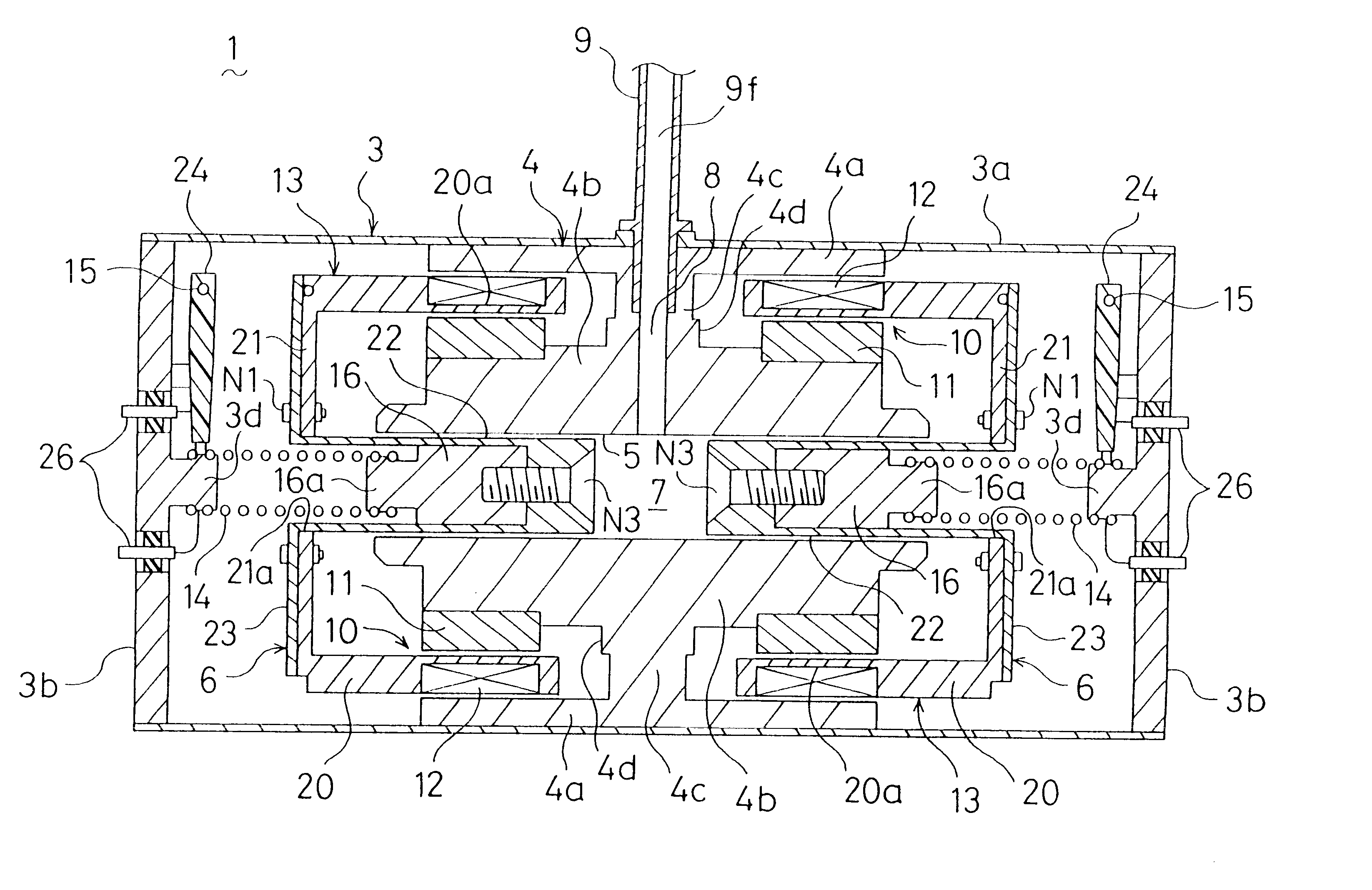
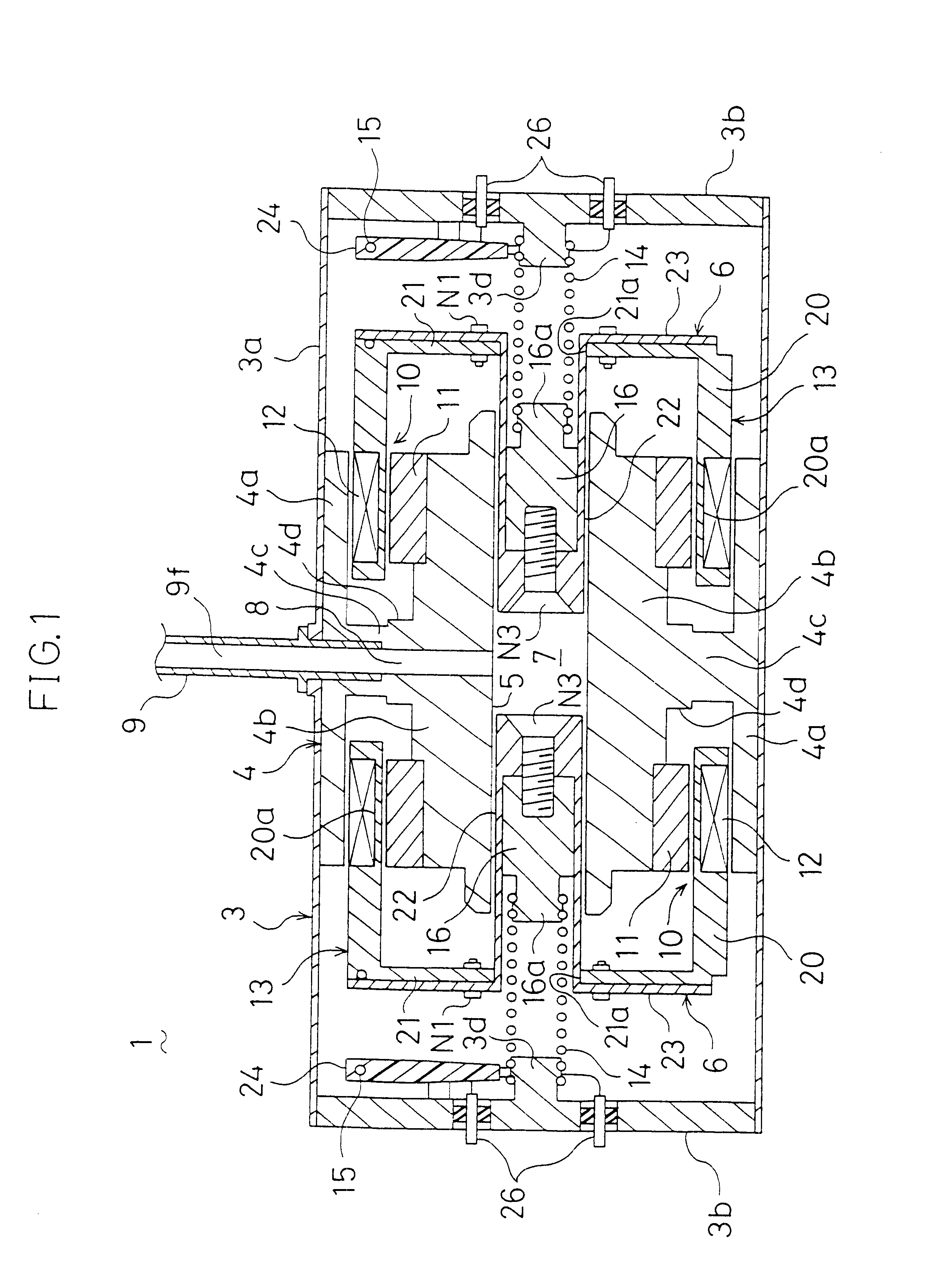
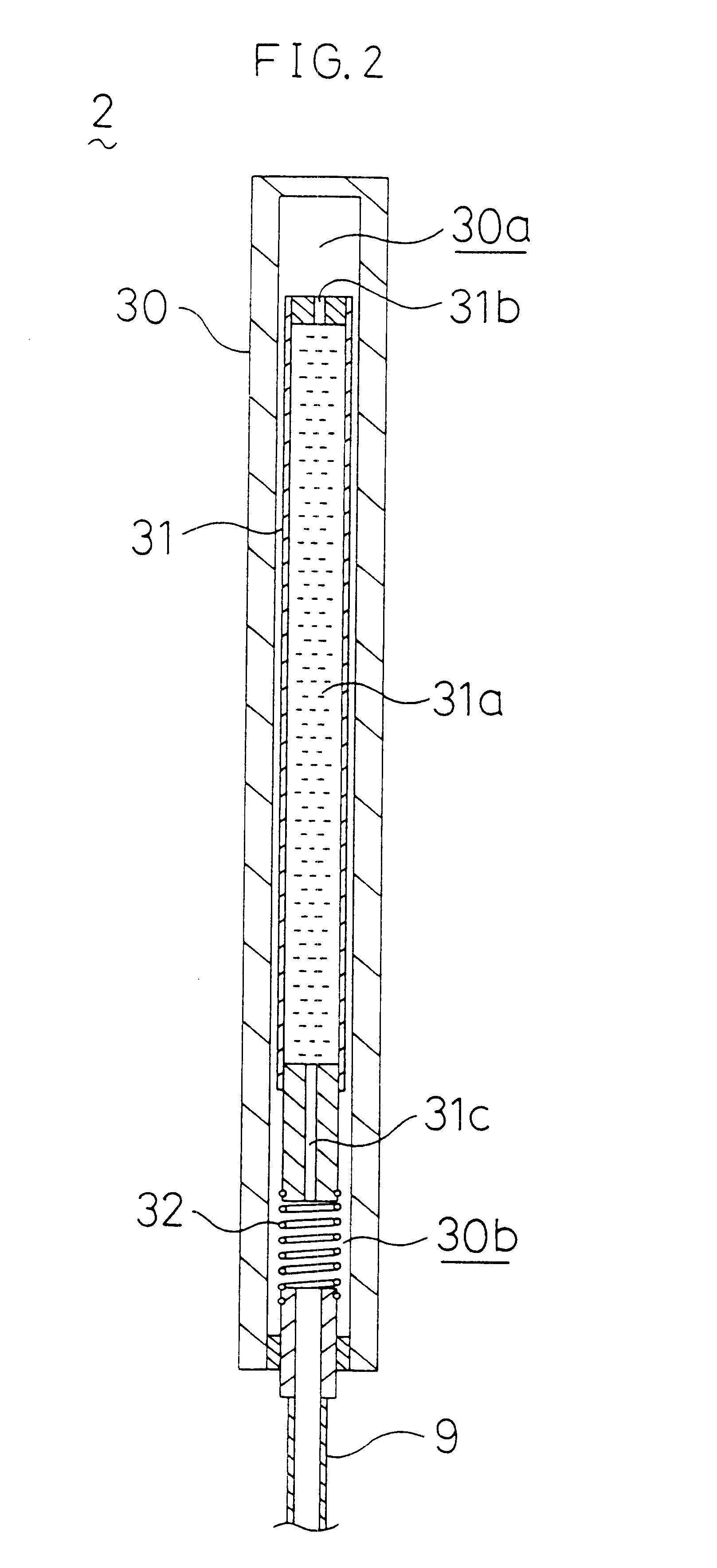
This invention relates to a Stirling refrigerating machine in which a compressor is connected to an expander through a connection pipe, and particularly relates to improvements of a sealing structure provided at a joint between the compressor and the connection pipe.A free displacer type Stirling refrigerating machine has been conventionally known as one of small size refrigerating machines which produce cold conditions at an extremely low temperature level. Such a refrigerating machine is disclosed in Japanese Patent Application Laid-Open Gazette No. 6-174321. The refrigerating machine is so composed that a compressor for compressing a gas refrigerant and an expander for expanding the gas refrigerant discharged from the compressor are connected to each other through a connection pipe.Below, description will be made about the structure of the compressor.As shown in FIG. 6, the compressor (a) includes a gastight casing (b), a cylinder (c) provided in the casing (b), a pair of pistons...

Claims


Application Information

Patent Timeline
IPC IPC(8): F04B35/00F04B39/12F04B35/04F25B9/14
CPCF04B35/045F04B39/123F25B9/14F25B2309/001
Inventor FUJIYAMA, NORIHIDEKOUSAKA, TADASHISOTOJIMA, TAKAZO
Owner SUMITOMO HEAVY IND LTD
Why Eureka
Try Eureka