Vehicular air-bag lid structure

Inactive Publication Date: 2002-10-08
CALSONIC KANSEI CORP
View PDF8 Cites 17 Cited by
  • Summary
  • Abstract
  • Description
  • Claims
  • Application Information

AI Technical Summary

Problems solved by technology

In the conventional vehicular air-bag lid structure, however, the outer skin, for example a vinyl chloride outer skin, of the instrument panel tends to elongate at high temperatures.
Moreover, because the door member has been formed so that its whole surface is of substantially uniform strength, it does no

Method used


Image

  • Vehicular air-bag lid structure
  • Vehicular air-bag lid structure
  • Vehicular air-bag lid structure

Examples


first embodiment

the present invention will now be described with reference to FIGS. 1-3 of the drawings.

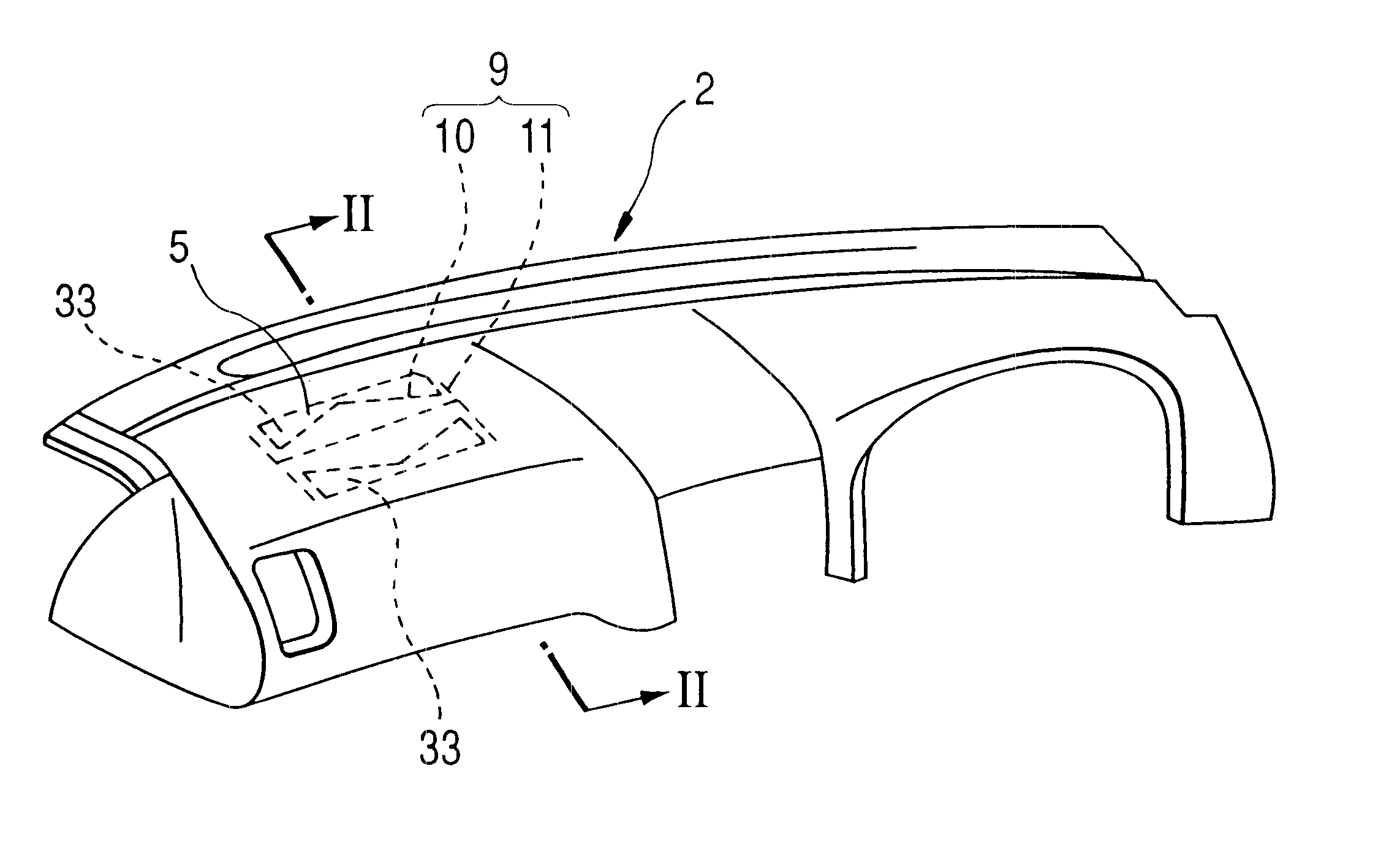
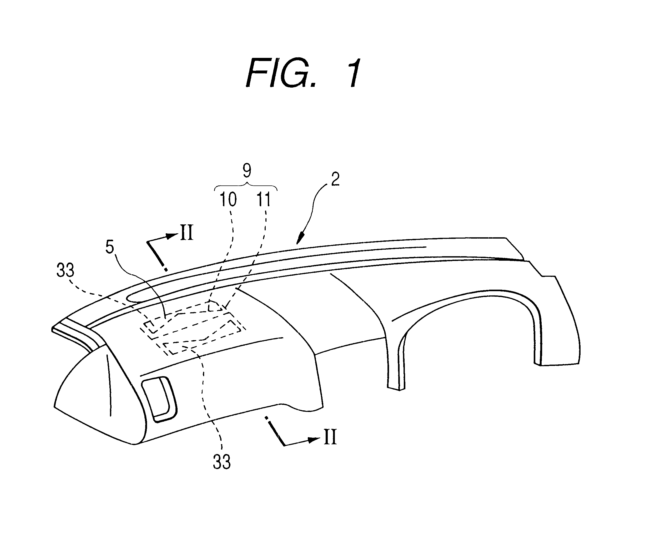
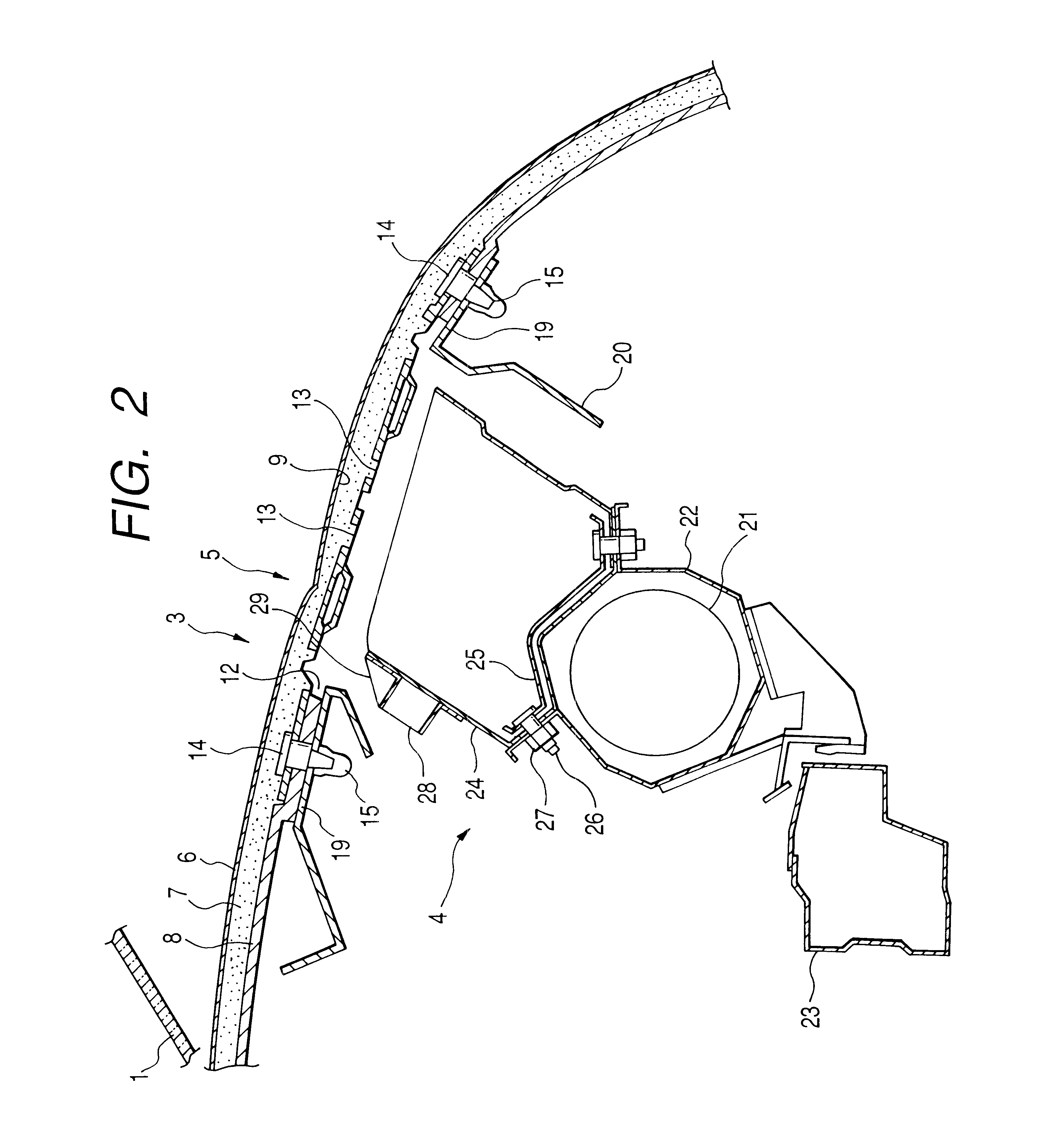
An air bag system 3 is installed on the passenger's side of an instrument panel 2, below the front window glass 1 of an automobile. The air bag system 3 includes an air bag module 4, and a lid portion 5. The air bag module 4 will be described later, is used to contain an air bag body, and is disposed within the instrument panel 2. The lid portion 5 forms, in a portion of the instrument panel 2, an inflation opening through which the air bag body is inflated. Although the lid portion 5 is formed integrally with the instrument panel 2, it may be formed separately therefrom.

The instrument panel 2 and the lid portion 5 each have a three-layer structure including an outer skin 6, a foaming layer 7, and a core material 8, in order from the outer surface side. The instrument panel 2 is formed by setting the outer skin 6 and the core material 8 in a foaming mold (not shown) and injecting a foaming agent ...

third embodiment

the invention will now be described with reference to FIGS. 5 and 6 of the drawings, wherein reference numeral 148 denotes a front window glass.

An instrument panel 120 according to the third embodiment of the invention has a three-layer structure similar to that shown in FIG. 1. That is, the instrument panel 120 includes a foaming layer 123 disposed between an outer skin 121 and a core material 122. Further, an air bag lid portion 124 is provided integrally with the instrument panel 120.

The outer skin 121 is made of TEO (Thermoplastic Elastomer of Olefin). The outter skin made of TEO has a tensile elongation that depends on temperature as shown in Table 1.

The air bag lid portion 124 is equipped with door members 126--a window-side door member 126a and a passenger-side door member 126b--capable of substantially blocking an opening 125 formed in the core material 122 on the underside thereof. Beneath the door members 126, a reinforcing guide 127 is brought into contact with and substa...


PUM


Abstract

A vehicular air-bag lid having a three-layer structure including an outer skin (6), a foaming layer (7), and a core material (8). Substantially square door members (13) are fitted within an opening (12) and are opened about a hinge portion at the time of air bag inflation. A pair of substantially triangular-shaped, in plan view, recessed bead portions (30) project toward the undersides of the respective door members (13). A reinforcing plate (31) accompanies the whole recessed bead portion on the surface side of each door member (13). Each recessed bead portion (30) has two of its three sides respectively disposed along the side of a door member (13) and along a hinge portion.

Description

1. Field of the InventionThe present invention relates to a vehicular air-bag lid structure.2. Description of the Related ArtSome vehicles such as automobiles are equipped with air bag systems as a safety device in case of emergency. Such an air bag system is designed to inflate an air bag body--that has been folded up and contained in a housing disposed in an instrument panel or the like--toward a person within a vehicle chamber by air pressure from an inflator when an impact exceeding a predetermined value is applied to a vehicle body. At that time, the bag body stops the head of the person seated in the predetermined position so as to prevent his head from hitting the instrument panel and the like.When the air bag body is inflated, it presses a lid portion formed in the instrument panel to form an inflation opening by cleaving grooves formed in the lid portion, so that the bag body is inflated from the inflation opening toward the person in the vehicle chamber.The instrument pane...

Claims


Application Information

Patent Timeline
IPC IPC(8): B60R21/20B60R21/2165
CPCB60R21/2165
Inventor NISHIJIMA, TAKAYUKI
Owner CALSONIC KANSEI CORP
Why Eureka
Try Eureka